
ARMAC Fire Defence System - Technical Notes Part C
Electronics and Control Systems
Development History
The electronic design for ARMAC went through several iterations. In the original design the Raspberry Pi (handling the Home Assistant dashboard and MQTT server bridge between the outside world and system, and one Arduino lived in the House, and that single Arduino commanded the system valves via relays by direct connection to the relay logic inputs via the multicore cable and also received and processed the sensor data on separate wires and transmitted the whole to the Raspberry Pi.. This proved electrically vulnerable to electromagnetic interference and even with hardening of various sorts components remained vulnerable, notably when the pump starter motor fired up.
In addition, in practice it was found that two Arduinos were needed to process sensor inputs transmitted also to the House over the multicore cable. This was getting pretty cumbersome, data received was not very reliable, and the relays tended to have a mind of their own. And, despite a range of steps to harden the system against electromagnetic interference, including separating power from relays and more fragile components, and the use of ferrite beads, filters, etc, things remained too fragile for a system that needs to be resilient under pressure.
It also became increasingly attractive to incorporate some level of autonomous decision making into the system so that if communication with the outside world was lost, the system could still continue to respond to an increasing (or decreasing) threat. The next move was to shift an Arduino into the pump shed to make autonomous decision making possible. This it was hoped it could when necessary command the relays by wiring the logic side of the relays with two wires, each protected by a one-way rectifying diode. One wire was to come from the house on the red underground multicore cable, and the other directly from the shed Arduino. The relay control wires were biased up by connection via a 10 k Ohm resistor to +5 Volt. In the end this approach still proved inadequate - it was vulnerable to signal collision, and cable noise.
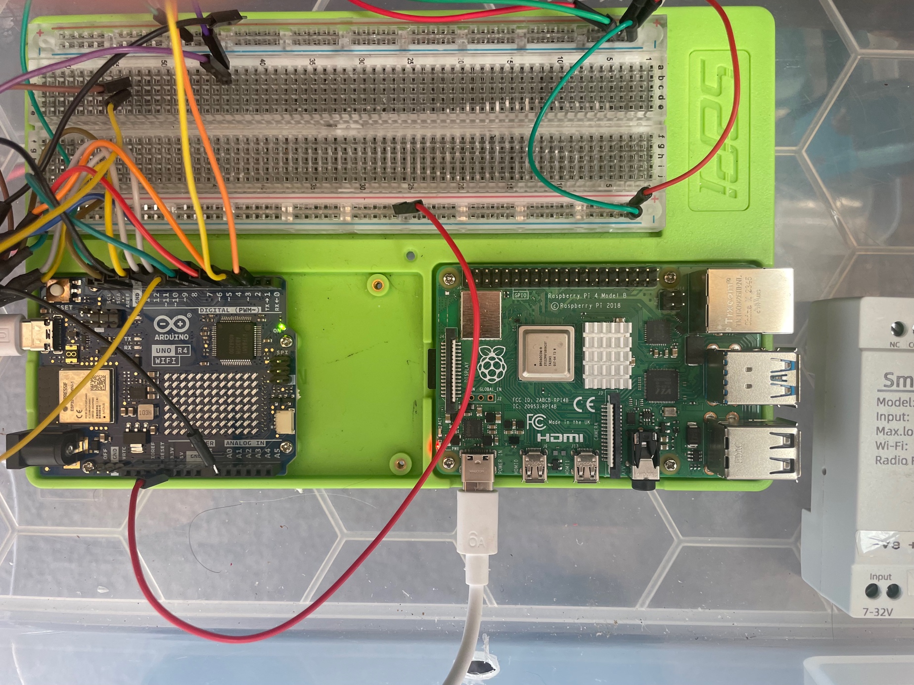
In the end I bit the bullet and decided to create the current system. This required a complete re-vamp of the system's electronic hardware and software. It introduced the current architecture of the House modules being responsible for communication with the external world, and the relays, sensor information, and autonomous decision making being carried out in the shed. The Raspberry Pi was relocated to the same place that the routers are linked to the external optical cable and all of that was supported by a large, continuously charged 12V battery. The rest was packaged into proper enclosures as modules.
Power between the shed and house was via a robust underground two core cable connecting the large pump battery with the a mains supported Victron 10 amp charger in the house. Properly protected by snubbers and other filters, DC Voltage Regulator modules were used to convert 12V DC to 5V DC or 24V DC as required.
The Relay Module
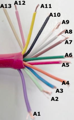
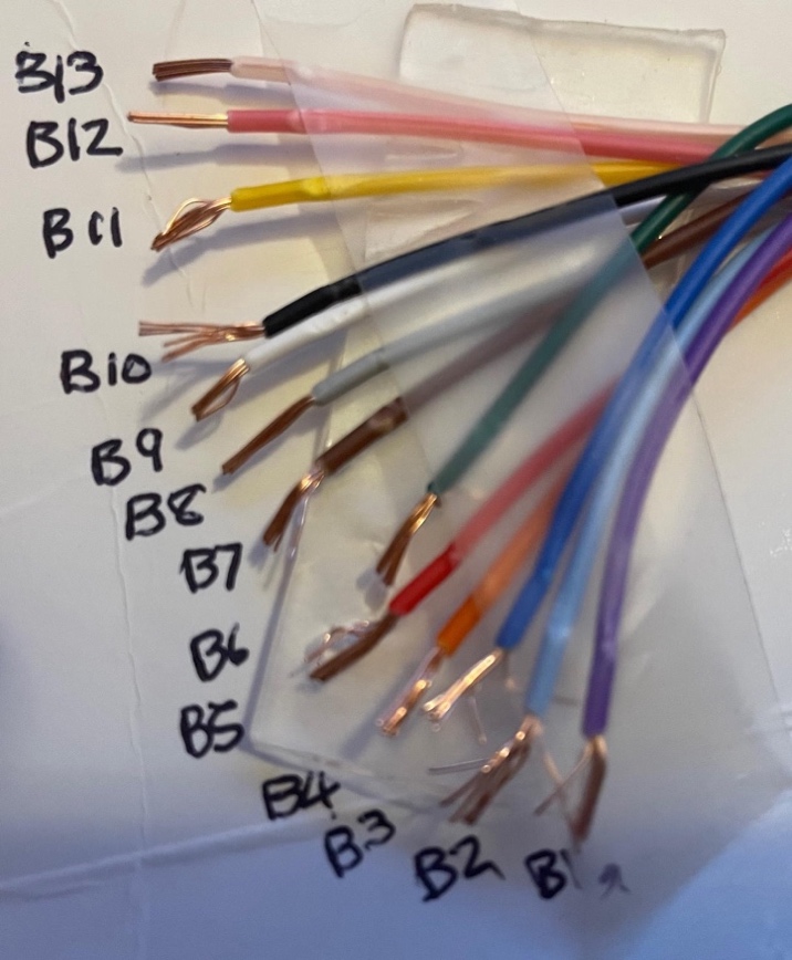
As described above this module contains the strip of Songle 5V input relays that operate the sprinkler system valves. The output side of each relay has N/C and N/O and power terminals. The relays are powered through a 12V to 5V step down module connected on the 12V side to the shed battery. The input logic side of the relays is linked to corresponding pins of Arduino AR3 by means of the blue multicore cable.
The relay module controls:
Pump Control Relays (Hardware Interlocked):
- Relay 1: Pump START (momentary)
- Relay 2: Pump STOP (momentary)
- These use Songe latching relays with hardware interlock
Valve Control Relays:
- Relay 3: Low/High pressure 3-way motorised valve
- Relay 4: Spray/Recirculation 3-way motorised valve
- Relay 5: Shed cooling solenoid valve (NC)
- Relay 6: Gel injection valve
Spare Relays:
- Relays 7-12: Reserved for future expansion
The Autonomous Module
This contains the Arduino Uno R4 wifi AR2 and AR3 modules. Arduino AR2 is connected to Arduino AR3 by a UNP peer-to-peer local wifi link and transmits the sensor data to A3 over this link.
The Autonomous module takes over and runs the system if it determines that effective contact has been lost with Remote Control Module. It determines this by monitoring a wire down which a regular �heartbeat� signal is sent from the Remote Control Module. If that fails after a pre-determined interval the Autonomous Module takes over control. It relinquishes control if the heartbeat resumes. The tasks are complex involving timing issues, and so two Arduinos (2 and 3) are assigned different aspects.
Arduino 2 acts as the central hub for the sensor set. It receives and processes all sensor signals from outside the shed, calculates numeric values, and then transmits them every 1 second by a local UDP wifi link to Arduino 3, and by an RS485 link over two wires of the multicore underground cable to Arduino 1.
Through the its two Arduinos (Arduino 2 and 3) the Autonomous module monitors
- Arduino 1 heartbeat
- Battery level at battery in shed
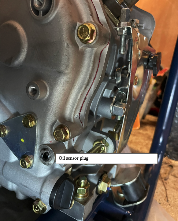
- Pump oil pressure
- Pump water pressure
- Ember attack sensor
- Temperature inside and outside the shed
- Tank water level
- Water Flow through the main pipe to the sprinklers
Arduino 3 carries out the logical decision making to continue to activate valves and relays in the shed if contact is lost for any reason with the Remote Control module.
In particular if communication with the Remote Control Module, or with the internet, is lost for 5 mins the Autonomous Control Module activates. Through Arduino 3 it consults pump oil pressure and water pressure and if both are low, assumes the pump is not yet working. If pump status is off, and the states below are reached, and communication with the House Control Module is still not occurring, then the Automatic actions listed are progressively implemented. If communication with the internet and House Control Module is restored, control is handed back to the remote control dashboard. Remote launching of the Autonomous Module is achieved by a switch in the remote control panel which changes the frequency of the Arudino-1 heartbeat from 1 Hz to 2 Hz when it is desired that the Autonomous Module take over. Toggling the switch in the control panel restores the frequency to 1 Hz and restores control to the panel. The successful take-over by the Autonomous model is read in the Arduino 1 by an input heartbeat from Arduino 3 which is registered in the control panel, and all sensors remain accessible to both the Arduino 1 and through it to the remote control panel, as well as the Autonomous model via Arduino 2.
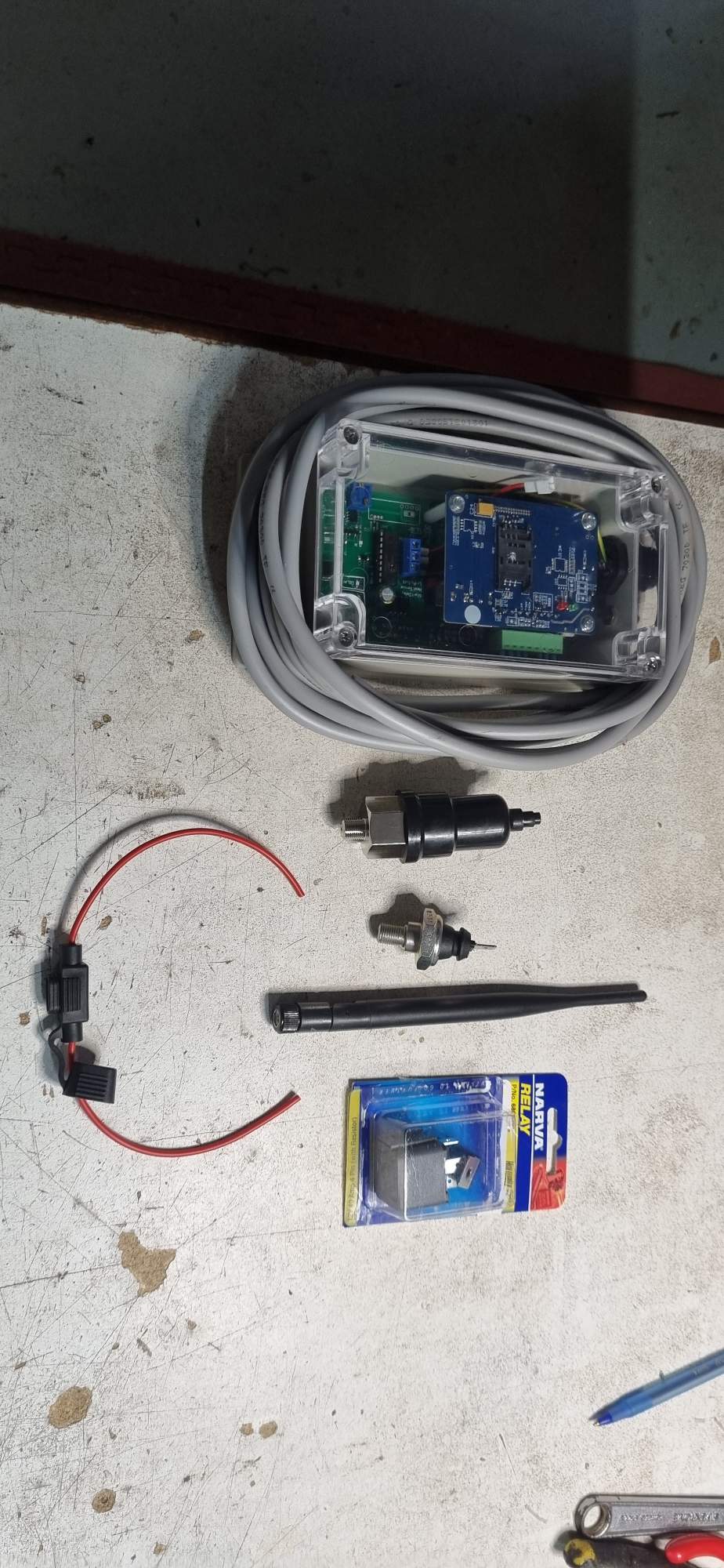
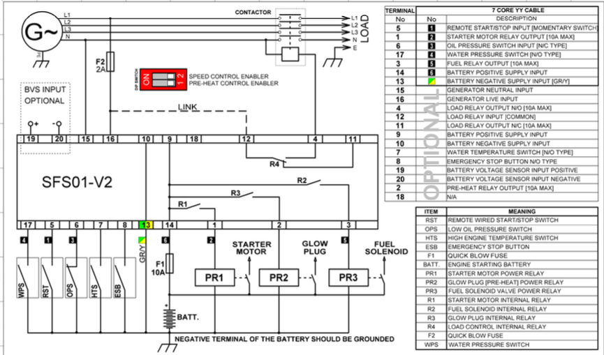
The SFS01Pump control Module (module 5)
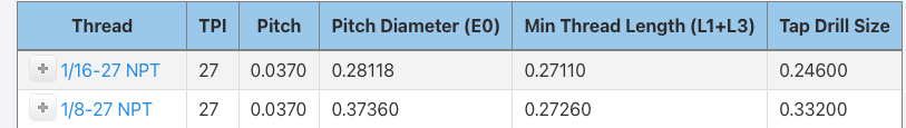
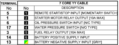
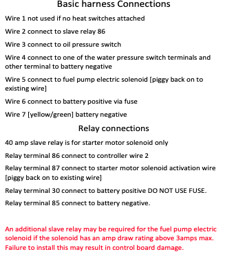
This module was developed and is provided on a commercial basis by Small Farm Systems. It is connected to the mobile G4 network, but also by a remote stop/start wire �wire 1� which activates the pump if its connection (from terminal 5 on the unit) to GND (terminal 13 on the unit) is broken. Thus the pump is activated when the N/C (normally closed) wire 1 circuit is opened. This will happen if one or more N/C switches placed in series in wire 1 are opened to set the pump running. The pump can later be turned off either by closing the circuit, or using the SMS Command �STOP�. The pump control module is connected to the external G4 mobile network. A 300x300 magnesium oxide panel is set into an aperture cut into the metal shed wall immediately adjacent to the module antenna, providing transparent access to the mobile signals.
The module terminals are wired to the pump electronics as as follows:
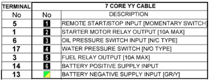
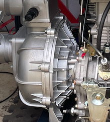
The module is directly wired with to the pump according to the above table and the module itself is situated next to the Autonomous and Relay Modules on a set of shelves on the right wall of the shed.
Relays and the Arduino reset
A critical issue with Arduino-controlled relays is that when the Arduino resets (power-on or watchdog reset), all digital pins briefly go to their default state. This can cause unintended relay activation.
Solutions implemented:
- Hardware interlocks on pump START/STOP relays
- Pull-down resistors on all relay control lines
- Software initialization that sets safe states within 50ms of boot
- Watchdog timer to detect and recover from hangs
Logic Table for Hardware Interlocked Songe Latch Relays (Pump Control)
| START Signal | STOP Signal | Pump State | Notes |
|---|---|---|---|
| LOW | LOW | Maintained | No change |
| HIGH | LOW | STARTING | Pulse applied |
| LOW | HIGH | STOPPING | Pulse applied |
| HIGH | HIGH | BLOCKED | Hardware interlock prevents |
The hardware interlock uses diodes and resistors to ensure that if both START and STOP signals are accidentally HIGH simultaneously, neither relay activates. This prevents damage to the pump control module.
Key Hardware Behaviors
- Power-on Reset: Arduino pins default to INPUT (high impedance). Pull-down resistors ensure relays remain OFF during the ~50ms boot time.
- Watchdog Reset: If the program hangs, the watchdog timer triggers a reset. The system returns to a safe state.
- Communication Loss: If RS485 communication from the house is lost for > 30 seconds, the autonomous module takes over.
- Sensor Failure: If a critical sensor fails, the system uses fallback logic (see Sensor Failure Fallback section).
Relay setting programming notes
Key points from the relay control code:
- All relay states are tracked in a state variable array
- Changes to relay states are logged to SD card with timestamp
- Before activating a valve relay, the code checks that sufficient time has elapsed since the last change (motorised valves need ~15 seconds to complete travel)
- Pump START/STOP commands are momentary pulses (200ms)
- Gel injection valve has a flow totalizer to prevent over-dosing
Example code structure:
void setRelay(int relayNum, boolean state) {
  if (relayState[relayNum] != state) {
    digitalWrite(relayPin[relayNum], state);
    relayState[relayNum] = state;
    logRelayChange(relayNum, state);
  }
}
Relay setting wiring notes
The relay board connections:
- Power: 12V supply from battery via fuse
- Control: Optoisolated inputs from Arduino pins
- Outputs: Relay contacts rated 10A at 240VAC
- LED indicators: Each relay has an LED showing state
- Protection: Snubber diodes across inductive loads
Wiring color code:
- Red: +12V power
- Black: Ground
- Yellow: Control signals from Arduino
- Blue: Valve control outputs
- Green: Pump control outputs
Tank Water Level Sensor installation
The tank water level sensor is an ultrasonic distance sensor (HC-SR04 style) mounted at the top of the tank. It measures the distance to the water surface and calculates the water level.
Specifications:
- Range: 2cm to 400cm
- Accuracy: �3mm
- Update rate: 1 reading per second
- Power: 5V from Arduino
- Output: Pulse width proportional to distance
Mounting:
- Sensor mounted in weatherproof enclosure
- Cable: 4-wire shielded cable
- Entry: Through sealed gland in tank roof
- Calibration: Zero level set at tank bottom
The sensor reading is converted to litres using:
litres = PI * (radius^2) * (tankHeight - measuredDistance)
where radius = 1.75m and tankHeight = 3.1m for our 30.3kL tank.
System response to Ember attack
When an ember trap is triggered, the autonomous module follows this logic:
- Immediate: Activate shed cooling (if not already on)
- Within 30 seconds: Start pump if not running
- Within 60 seconds: Switch to low volume spray mode
- Monitor: External temperature and rate of rise
- Adjust: Switch to high volume if temp > 65�C or rate > 10�C/min
- Cycle: Enter intermittent mode if no further ember detections for 10 minutes
Inter-Module Communication
Communication between the house module (AR1) and pump shed modules (AR2, AR3) uses RS485 serial protocol over a 2-wire twisted pair cable.
RS485 Advantages:
- Differential signaling (immune to electrical noise)
- Long distance capable (>100m, we use 10m)
- Multiple devices on same bus
- Robust in harsh environments
Protocol:
- Baud rate: 9600 bps
- Data format: 8N1 (8 data bits, no parity, 1 stop bit)
- Message format: STX + Command + Data + Checksum + ETX
- Timeout: 5 seconds
- Retry: 3 attempts before failover to autonomous
Message Types:
| Command | Direction | Purpose |
|---|---|---|
| PUMP_START | House -> Shed | Start the pump |
| PUMP_STOP | House -> Shed | Stop the pump |
| SET_MODE | House -> Shed | Change spray mode |
| GET_STATUS | House -> Shed | Request sensor readings |
| STATUS_DATA | Shed -> House | Sensor data response |
| EMERGENCY | House -> Shed | Emergency activation |
| HEARTBEAT | House <-> Shed | Communication check |
The heartbeat message is sent every 10 seconds. If 3 consecutive heartbeats are missed, the system assumes communication failure and the autonomous module takes over.
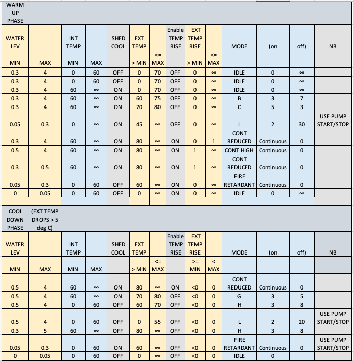
Criteria for Automatic actions in the Autonomous mode
The autonomous module makes decisions based on a decision matrix:
|!!! Criteria for Automatic actions in the Autonomous mode
The autonomous module makes decisions based on the following conditions:
Ember Attack Response:
- Condition: Ember trap triggered
- Action: START pump, Low volume mode
- Notes: Immediate response
Fire Front Approaching:
- Condition: External temp > 65�C
- Action: Maintain pump ON, High volume mode
- Notes: Fire front approaching
Rapid Temperature Rise:
- Condition: Temp rise > 10�C/min
- Action: Maintain pump ON, High volume mode
- Notes: Rapid fire approach
Moderate Threat:
- Condition: Temp 45-65�C
- Action: START pump, Low volume mode
- Notes: Moderate threat level
Low Threat / Conservation:
- Condition: Temp < 45�C, no embers for 10 min
- Action: Intermittent mode, Recirculation
- Notes: Conserve water
Battery Protection:
- Condition: Battery < 12.0V
- Action: Maintain state, Valve switch only
- Notes: Preserve battery
Tank Protection:
- Condition: Tank < 2000L
- Action: STOP pump
- Notes: Protect pump from running dry
Manual Override:
- Condition: Manual command from dashboard
- Action: As commanded
- Notes: Dashboard takes priority over autonomous logic
The autonomous module also implements hysteresis to prevent rapid switching:
- Temperature must drop 5�C below threshold before downgrading mode
- Ember trap must be clear for 10 minutes before reducing spray
- Mode changes are rate-limited to once per 5 minutes
Sensor Failure Fallback
If sensors fail, the system uses these fallback strategies:
| Failed Sensor | Fallback Strategy |
|---|---|
| External temperature | Use internal temp + 20�C estimate |
| Internal temperature | Assume 50�C if pump running |
| Flow sensor | Use mode-based flow estimate |
| Tank level | Assume 50% capacity |
| Battery voltage | Assume 12.5V, disable pump cycling |
| All ember traps | Rely on temperature sensors only |
| Camera | Continue with other sensors |
Multiple sensor failures trigger a warning message (if communication available) and the system defaults to a conservative strategy: low volume spray with recirculation cycling.
System Testing: The TestSys Module
A dedicated test system is implemented to verify correct operation without actually spraying water:
- Test Mode Activation: GPIO pin 11 on AR3 jumpered to ground
- LED Indicator: Shows system is in test mode
- Relay Monitoring: All relay commands logged but not executed
- Sensor Simulation: Can inject simulated sensor values
- Communication Test: Verifies RS485 links
- Valve Position: Displays intended positions without moving
Test scenarios include:
- Ember trap activation sequence
- Temperature rise simulation
- Communication failure
- Low battery response
- Tank low level
- Sensor failures
Voltage surge circuit protection
The electronics are protected against voltage surges using:
- TVS Diodes: Bidirectional transient voltage suppressors on all sensor inputs
- Varistors: Metal oxide varistors on power supply inputs
- Fuses: Inline fuses on all power feeds
- Optoisolators: Isolate Arduino outputs from relay coils
- Common mode chokes: On RS485 communication lines
These protections are essential because:
- Pump starting creates voltage spikes
- Solenoid valves generate back-EMF
- Lightning strikes can induce voltages in long cables
- The shed is partially a Faraday cage (can build up static)
Parallel circuit protection
Where multiple sensors or devices share power or signal lines, protection includes:
- Individual fuses: Each device has its own fuse
- Isolation diodes: Prevent one failed device affecting others
- Pull-up/pull-down resistors: Ensure defined states
- Bypass capacitors: Filter local noise

LCD DISPLAY in shed of key parameters in real time
A 20x4 character LCD display mounted in the pump shed shows real-time system status:
Line 1: Pump state, Mode, Battery voltage Line 2: External temp, Internal temp, Flow rate Line 3: Tank level (%), Ember traps status Line 4: Communication status, Autonomous/Manual mode
Example display:
PUMP:ON HI-V  12.8V
ExtT:58C In:42C 145L
Tank:67% Emb:-- --
WiFi:OK  MANUAL
The display updates every 2 seconds and provides valuable local monitoring without needing to access the dashboard.
Protection against voltage surge and spikes
Additional protection measures beyond those already mentioned:
- Input filtering: RC low-pass filters on all analog inputs
- Ground plane: PCB with solid ground plane
- Star grounding: Single point ground for all electronics
- Shielded cables: For sensors exposed to electromagnetic interference
- Ferrite beads: On power and communication cables

Protection of electronic components from water spray incident
Although the pump shed is designed to be cooled by water spray, the electronics must be protected:
- Waterproof enclosures: IP65 rated boxes for all electronics
- Cable glands: Sealed entries for all cables
- Elevated mounting: Electronics mounted high in the shed
- Drainage: Enclosures have drain holes at bottom
- Desiccant packs: Inside enclosures to absorb moisture
- Conformal coating: PCBs coated with protective lacquer
The Arduino modules are in separate enclosures from the high-voltage relay boards to minimize risk.
Pump Control Module setup
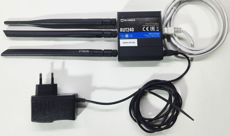
The commercial pump control module (from pump supplier) includes:
- LTE modem (G4) with SIM card
- Relay outputs for remote START/STOP
- SMS command interface
- Input terminals for external control
- Battery voltage monitoring
- Run-time hour meter
Integration with our system:
- Our relay module (AR2) connects to the external control terminals
- Pump status is read back via a voltage sense line
- SMS commands provide backup control if RS485 fails
- Hour meter data is logged for maintenance scheduling
SMS Commands:
- START - Starts the pump
- STOP - Stops the pump
- STATUS - Returns pump state, runtime, battery voltage
Electronically controlled Valves
The system uses two types of electronically controlled valves:
Motorised 3-way Valves (2 units):
- Type: Ball valve with electric actuator
- Power: 240VAC (via relay)
- Travel time: 15 seconds
- Positions: A-AB-B (3 positions)
- Feedback: Limit switches at each end position
- Used for: Low/High pressure, Spray/Recirculation
Solenoid Valves (1 unit):
- Type: Normally Closed (NC)
- Power: 12VDC (via relay)
- Response time: <1 second
- Used for: Shed cooling spray
The motorised valves have internal limit switches that cut power when the valve reaches the commanded position. This prevents overdriving the motor.
Sensors
The system employs multiple sensor types:
| Sensor | Type | Range | Accuracy |
|---|---|---|---|
| External temp | DS18B20 | -55 to 125�C | �0.5�C |
| Internal temp | DS18B20 | -55 to 125�C | �0.5�C |
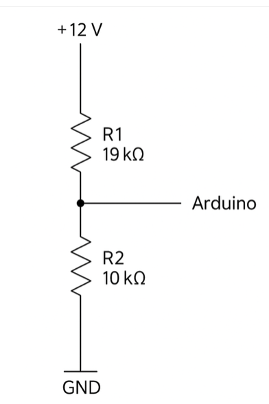
| Battery voltage | Resistor divider | 0-15V | �0.1V |
| Flow rate | Hall effect | 1-100 L/min | �2% |
| Tank level | Ultrasonic | 0-4m | �3mm |
| Ember trap | Thermistor | 0-300�C | �5�C |
| Flame | IR photodiode | 720nm | 1m range |
All sensors are read by Arduino AR3 and the data is sent to AR1 for dashboard display and to AR2 for relay decision logic.
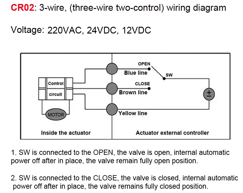
Motorised 3-way (and 2-way on/off) valves
The motorised valves are controlled by applying 240VAC to the motor for the duration needed to move the valve to the desired position.
Valve 1: Low/High Pressure
- Position A: Low pressure (180 kPa) - bypass restrictor
- Position B: High pressure (420 kPa) - through restrictor
Valve 2: Spray/Recirculation
- Position A: Spray to sprinklers
- Position B: Recirculate to tank
The Arduino tracks the current position and only activates the relay if a change is needed. Travel time is 15 seconds, so the code waits 20 seconds between commands to the same valve.
Switching the Valves using a single Songe 2-way relay
Each motorised valve requires reversing polarity to switch direction. This is accomplished using a DPDT relay configuration:
Relay OFF: Motor + to L, Motor - to N  (Position A)
Relay ON:  Motor + to N, Motor - to L  (Position B)
The limit switches in the valve cut power when the valve reaches the end of travel, so the relay can remain energized without damaging the motor.
Programming the microcomputers
All three Arduino modules (AR1, AR2, AR3) are programmed in C++ using the Arduino IDE. The programs include:
AR1 - Remote Control Module (House):
- Blynk library for dashboard
- RS485 communication library
- Watchdog timer
- ~1800 lines of code
AR2 - Relay Module (Shed):
- Relay control functions
- Inter-module communication
- SD card logging
- ~1300 lines of code
AR3 - Autonomous Module (Shed):
- Sensor reading and filtering
- Decision logic
- Failover handling
- ~2100 lines of code
Key libraries used:
- OneWire and DallasTemperature (for DS18B20 sensors)
- SoftwareSerial or HardwareSerial (for RS485)
- SD (for logging)
- Blynk (for AR1 dashboard)
Example sensor reading code:
// Read external temperature
sensors.requestTemperatures();
float extTemp = sensors.getTempCByIndex(0);

// Apply simple averaging filter
extTempFiltered = (extTempFiltered * 0.9) + (extTemp * 0.1);
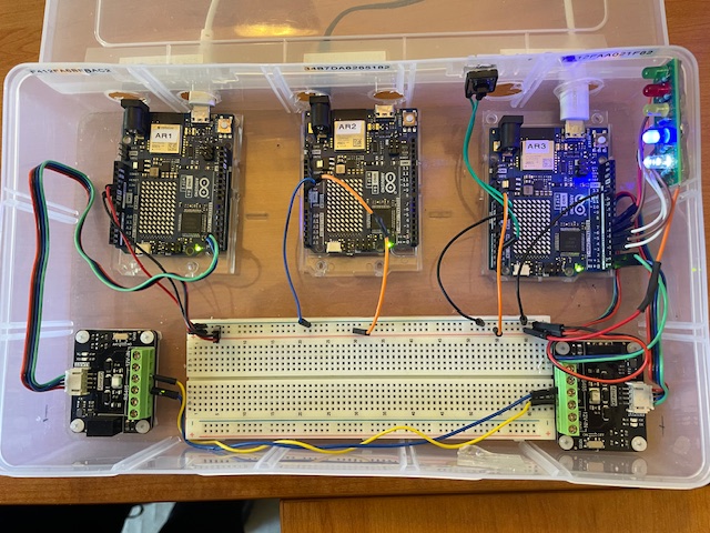
Bench Testing the Programmes
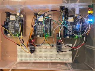
Before installation, all programmes were extensively tested on a bench setup:
- Hardware simulation: Potentiometers to simulate sensors
- LED indicators: Show relay states without connecting valves
- Serial monitor: Display all variables and logic states
- Simulated inputs: Inject test conditions (high temp, low battery, etc.)
- Communication test: Two Arduinos connected via RS485
Test scenarios validated:
- Normal operation sequences
- Sensor failure detection
- Communication loss and recovery
- Autonomous mode activation
- Battery low response
- Emergency shutdown
- Mode transitions
Only after passing all bench tests was the code deployed to the actual hardware in the shed.
<< | | >> |Table of Contents>