
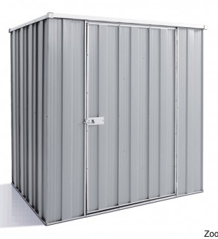
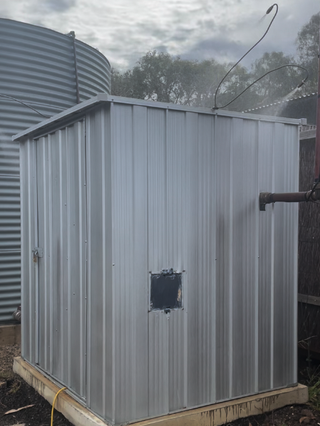
Tank and pump shed.
The lower DN50 copper pipe is the inlet from the tank to the pump. The upper DN20 pipe recirculates water to the tank when the system is in test or during the off phase of the intermittent cycle (when battery voltage < threshold). The tank water level sensor cable in a protective silicone sleeve is attached to the recirculation pipe.
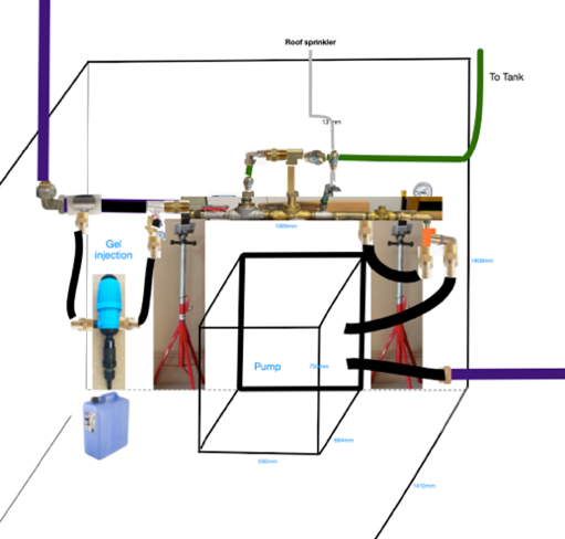
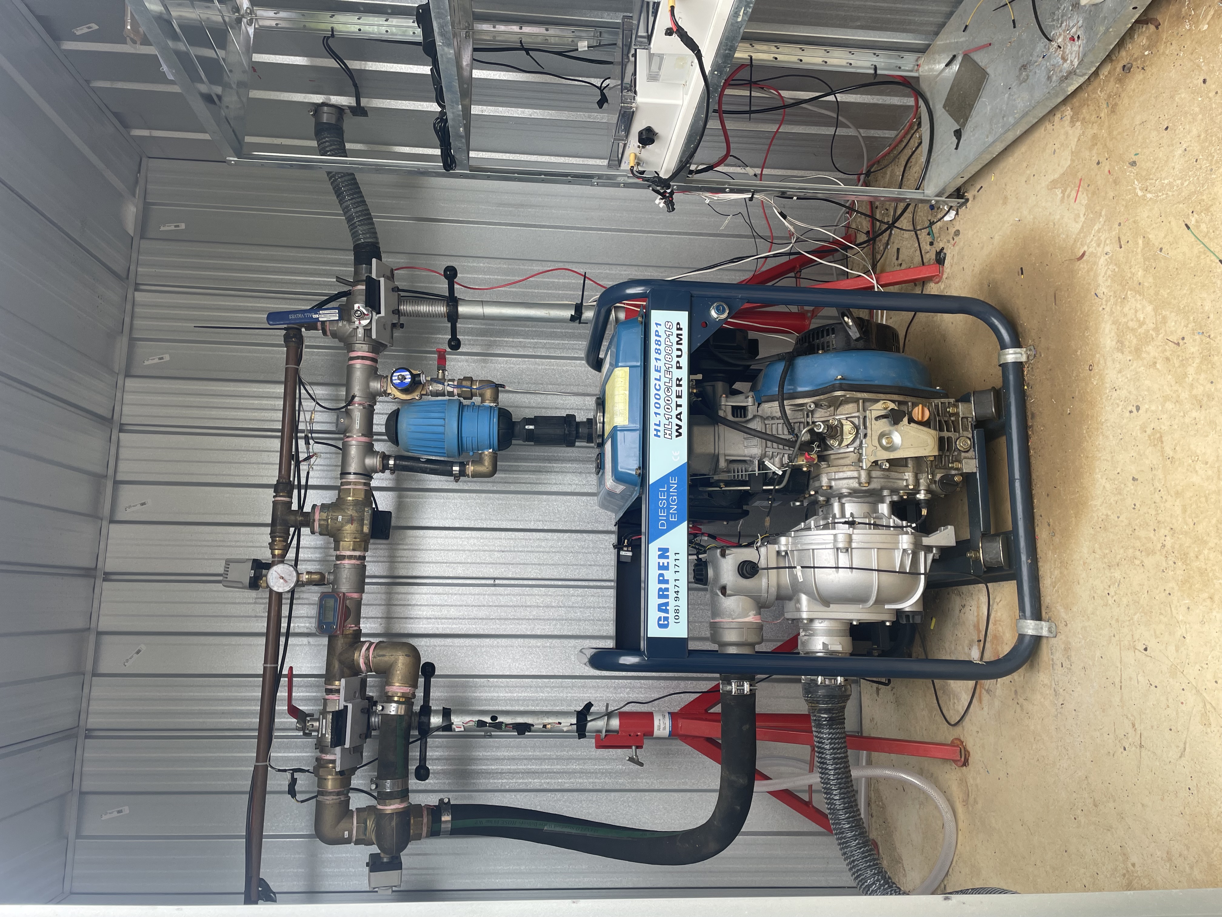
Layout of plumbing in Pump Shed
Planned
Final
 |
Outline of the water control system
The water system is controlled by an electronic system based on multiple layers of communication and control to increase resilience in the event of failure of one sub-system under the pressure of a fire emergency.
The pump itself has its own commercially constructed pump control module, and that can be operated directly by mobile network text messages, but also by external signals coming through one of its terminals.
The pump shed, being all metal and thus a near 'Faraday Cage', is not a good place to receive wifi, even though a magnesium oxide window (transparent to wifi and mobile network signals) has been set into the side of the shed where the pump control module is situated. In order to ensure excellent wifi connectivity and insulate the more sensitive electronics from heat, the bulk of the electronics are established in the house, with an underground multicore cable connecting the house control system with the shed controls.
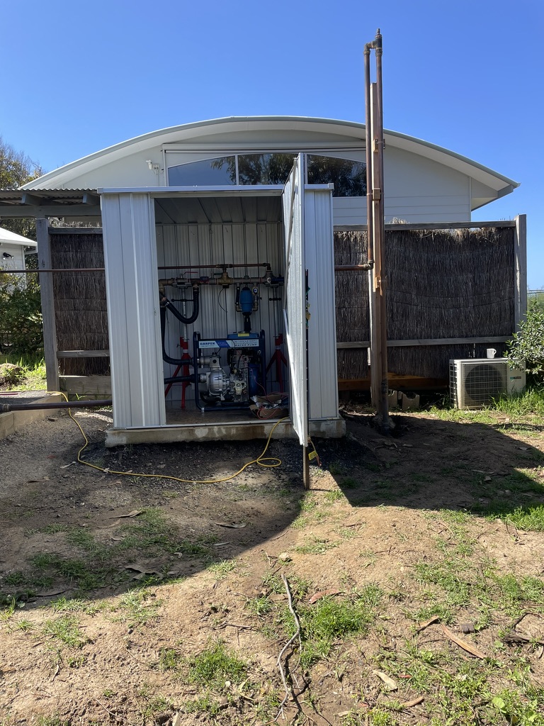
Various devices (pumps, sprays, and sensors) are controlled or monitored remotely via a dashboard which can be accessed online via a mobile phone (iOS/Android), or tablet, or computer. A backup wifi router is established and powered from a battery charger/inverter, and is connected through an LTE SIM card, to enable automatic fallback wireless connections if the normal network/wifi becomes unavailable. In the shed a series of sensors provide information about the state of the system, whilst relays operate operate various valves and the pump as described below , allowing the system to operate in a series of different modes depending on the intensity of heat at the time. The somewhat steam punk setup seen below is the water control mechanism.
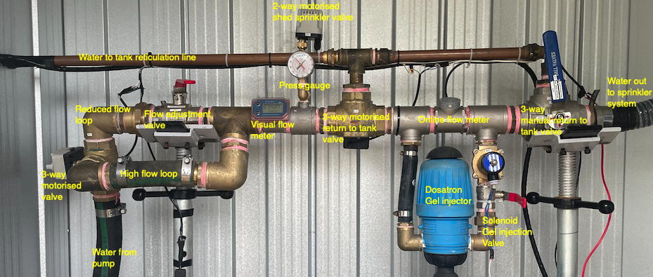
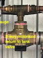
Water enters under pressure from the pump, rising up the vertical hose on the far left into the horizontal control pipe, and exits to the sprinkler system on the far right. Two pipes can be seen: the 50mm internal diameter lower control pipe and above it, the 20mm reticulation pipe that by means of the 3-way manual valve on the far right returns water to the tank, either providing a test loop or, via the electronically controlled 3-way valve in the center, an intermittent (on-off) timed cycle.
On the far left water either passes through the pipe with the pre-set ball valve determining the level of reduction in flow, or in its entirety as a full flow through the loop below, as determined by another motorised 3-way valve.
To the left of the centre water a tee-branch allows a modest flow of water to be diverted off through a manual valve, and then a motorised 2-way valve to the shed external cooling sprays. Finally to the right of centre can be seen the Dosatron gel-injection loop, controlled by a solenoid (on/off) and manual ball valve [this part requires at minimum presurisation on the left-hand input branch - intended to be achieved with an electric pump - and is still under development].
Set into the main 50mm control pipe are from left to right, a visual display flow meter, a pressure gauge, and above the Dosatron an online wired in flow meter. Other sensors not in the picture include a water depth sensor in the tank, and two temperature sensors, one inside the shed and the other outside. The external cable to the water depth sensor is protected with a high temperature resistant silicon sleeve.
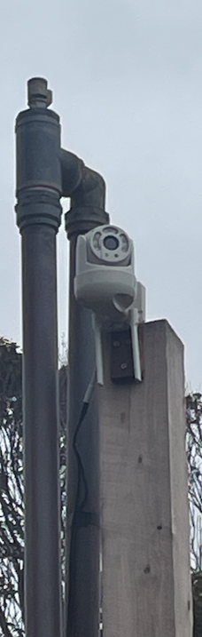
Finally, visual contact is available from a video cam mounted on the vacuum breaker pole. Of course, external sensors are expected to end up being destroyed if a fire front is present, and in that sense are considered sacrificial. Where this happens calculation based on what is sensed inside the shed takes over. For example, if the tank water level sensor is destroyed, the remaining depletion of water is calculated from the measured flow of water through the system and if that fails average flow rates for the different modes are utilised.
More detail on the interconnection of this water control system with the electronic systems is provided later in these Notes.
Pipe Supports
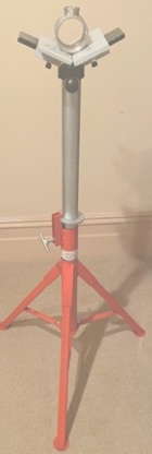
The pipe work is supported by two steel pipe-welders stands (obtained second-hand on Gumtree for $80). They were both moveable and adjustable in particular facilitating the testing and construction phases.
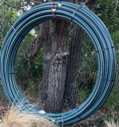
Feeder pipe
See earlier consists of 100 meter of 63mm blue line high pressure buried polypipe
Pump
Suitable pressure and flow is provided by a Garpen 3 inch 11 HP Diesel Pump WP3DELHPS with electric start ($1601) mounted on the shed concrete floor.(Appendix 1) with the following specifications: Max head 70m = 105 psi = 105x6.894 kpa = 720 kPa Max flow = 620 l/m (should easily service the 95-200 l/m required in this system) Dimensions= 500 long x 600 wide x 900 high mm Solenoid in fuel line to enable online stop and start. Pump uses about 2l/hr diesel and holds 12l in its tank so should run for 6 hours.
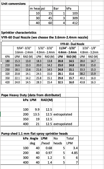
Actual performance is less in practice than the specs. Graham Lund formerly at Small Farm Services has carried out a bench test. The pump performance is shown below:
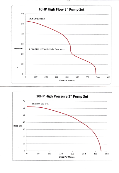
From the above, bench tested with 2 inlets and outlets, the WP3DELHPS with a 3 to 2 reducer on the outlets should realistically produce a 50 m head at 130 lpm and 45 m head at 300 lpm. From discussion on flow below this can be seen to work well. Maximum loss of head from elevation of sprinklers is no more than 5 meters which is unimportant. Pipe friction, as calcuated later is also trivial.
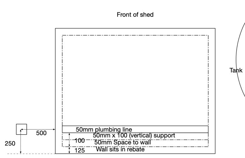
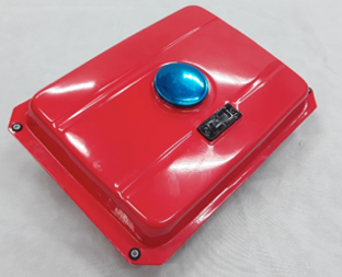
Pump Shed
The Garpen pump (dimensions h .75 x d 0.664, w 0.55 meter) are housed in a metal shed with stainless steel exhaust pipe, ventilation and inlet and outlet holes added as required. The contents the pump, controllers and valves - are to be protected by a sprinkler on top of the Pump Cover. A Yardstore F54 ZN flat roof 1.76wx1.410dx 1.800h single hinged door shed with anchor hooks provided and a 15 year warranty from Shed Stores was selected, ordered and constructed.
Pump shed protection
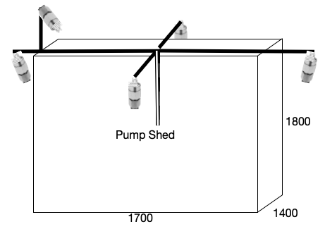
Keeping the pump shed cool via sprayed on water is likely to be important as a fire front approaches. In this design shed cooling is achieved using using 5 flat fan spray nozzles calibrated to spray around 5 l/m over the entire sheds 13.54 square meters of walls and roof in full pressure mode = 0.37 l/meter squared per min. At 100 deg C heat absorbed through evaporation is 2256 kJ/kg water and 5 l is 5 kg. If we assume 20% evaporates and rest is lost to the environment we cooling power of about 2.8 kW/meter squared, or for 50% 94 kW/m squared. This can be compared with the bushfire radiant heat flux for BAL-12.5 to BAL-19. For higher BAL we are relying on the surfaces staying wet.
 |  |
Flat fan 1.1 mm nozzles (stainless steel 304 which can be mated with brass) � inch BSPT, was available on Aliexpress for 7 for $48 were purchased with characteristics as shown.
Pump shed ventilation
The diesel pump requires air ingress and some level of heat disipation from the spray cooling or supplemented by venting. However, venting would prove counter-productive if the external ambient temperature rises above that in the cooled shed.
In the future, if deemed necessary, a Fire Damper window could be inserted into the wall opposite the pump air intake. Fire dampers close at around 100 deg C (for Sodium Silicate slats) automatically when a fire present temperature is reached. One example is the Lorient LVH44 Intumescent Fire Damper 100x100 galvanized part available from ASSA Abloy for $74.09 (excl GST). Another using Sodium Silicate is the Kilargo IFD44-L 100x100 which also sells for the trade price of $97. It is available from Idealair. An alternative would be a Curtain Fire Damper which is designed so that a series of blades in a frame descend and interlock when a fusible link set at a specified temperature is broken.
In the current setup we rely simply on shed cooling, with air ingress through the gaps in the shed, with the pump exhaust vented through a 2 stainless steel pipe extending in from a pentration in the shed wall coupled by a 400mm 40mm diam silicon hose to the pump exhaust, both of which were purchased on Aliexpress.
Consideration of further insulation
Some consideration was given to lining the pump shed with insulation board. However, this was not done for several reasons:
- The shed cooling sprays keep the external temperature of the shed down
- The insulation would need to be fire-rated
- The diesel pump can operate at quite high ambient temperatures (practical experience suggests well above the manufacturer's stated maximum)
In the future, if deemed necessary, it would be possible to add a fire-resistant lining to the pump shed. A suitable material would be Fire Crunch board which is constructed from glass fibre reinforced MgCl2 and rated as appropriate to BAL40 or FZ(Flame Zone).
An alternative is to wrap fire-vulnerable fittings (circuit boards, plastic covered ball valve motors, and dosatron gel injection module) in fire-resistant thermal insulating material. A good range of suitable materials are available on Aliexpress. However, at this point insulation has not been included other than wrapping the dosatron in an insulating blanket.
Water system components
The water system is composed of:
- 30.3 kL water tank (3.5m diameter x 3.1m high)
- Diesel pump (Garpen)
- Pump control module (commercial unit with LTE connectivity)
- Remote control system (Blynk dashboard via mobile/tablet/computer)
- Autonomous control system (Arduino-based)
- Sprinkler system (impact and fan spray heads)
- Valve control system (motorised 3-way and solenoid valves)
- Sensor system (temperature, flow, water level, ember detection)
- Communication system (WiFi with LTE failover)
Water can be conserved by setting flow on the minimum required to operate the sprinkler system. The flow from the pump passes through a ball valve which allows flow to be set in either high (about 250 L/min) or reduced flow mode (about 170 L/min. When high flow is required, the reduced flow loop is by-passed using a motorised 3-way valve which, when opened, allows maximum flow to be delivered through a high pressure loop to the sprinkler system.
Tank
A 30.3 kl tank (3.5m diam, 3.1 m high) from gettanked.com.au ($5,850 delivered) in shale grey colorbond, was mounted on a crushed rock base as specified. A replenishment pipe from the house mains runs to the top of the tank, and thence to a float valve to help maintain maximum available water. At 170 L/min the tank capacity (without replenishment) would be be sufficient for 3 hours and 8 mins spray or up to , say,10 hours in low flow with intermittent modes as described later.
The tank specifications are:
- Capacity: 30,300 litres (30.3 kL)
- Dimensions: 3.5m diameter x 3.1m height
- Material: Colorbond/Aquaplate steel
- Outlet: DN50 (2" internal diameter)
- Inlet: 3/4" with float valve
- Water level sensor: Ultrasonic (mounted at top)
The tank is replenished from the mains water supply via a 3/4" stainless steel float valve which automatically refills the tank after use. The valve is rated to 1 MPa which exceeds normal residential water pressure (0.3-0.5 MPa).
Copper Pipe Risers to Sprinklers
Each sprinkler is fed from the feeder pipe via a copper riser. The risers are:
- Material: Type B copper pipe
- Sizes: 15mm or 20mm depending on sprinkler
- Fittings: Brass compression or flared fittings
- Valves: Brass ball valve at each sprinkler for individual control
- Connection to feeder: Saddle clamp with brass compression fitting
The copper risers run underground from the saddle clamps on the feeder pipe up to ground level where they connect to the brass adjustable sprinkler mounts.
Anti-Syphon Control
To prevent water continuing to flow through the sprinklers which are below the level of the pump when the pump stops, a Vacuum breaker comprised of an outlet to allow air ingress when the water is not under pressure and a check valve to hold water under pressure is installed at the high point in the system.
 |  |
Flow, pressure and sprinkler requirements
Sprinkler heads A large number of sprinkler heads are available. Requirements include all metal and robust construction, easily removed and cleaned nozzles, and part-circle adjustable spray, and appropriate radii of spray for the pressures in the system. After considering these requirements the following were selected as potentially appropriate:
1. 3 x The Dural VYRSA-60 dual nozzle 3.6mm 2.4mm is designed to operate between pressures of 180-420 kpa corresponding to 13.0-14.5 m radius and 15.3-24.0 l/min. It will spray to a 13 m radius at a pressure of 180 kpa and to 14.1 at 20.8 lpm at 320 kpa. The pump develops max actual pressure max of 55-40 m head between 0-400 lpm. Given there will be little pipe friction in the 50 mm polypipe this system should be able to operate 3 of these sprinklers with no problems. Larger nozzles were available but were not utilised as whilst they would increase flow that would decrease duration of water availability.
2. The Pope Heavy Duty Impact sprinkler head (Appendix 4) is also sold for fire fighting (for example, the Rainmaker Sprinkler which is supplied with a gutter attachment.) It has a brass nozzle, adjustable full or part circle sprinkler head, and operates at a minimum operating pressure of 100 kPa and was available from Dural Irrigation ($23.73) or Bunnings. Specifications include: a heavy duty brass impact sprinkler; Full or part circle; 1/2" thread; 10LPM @ 100kPA, 18.9LPM @ 350kPA; 12.5 m maximum radius; Stainless steel springs; 1 Year Warranty https://www.popeproducts.com.au/sprinklers/heavy-duty-impact-sprinkler-head
More detailed calculations, which follow, support the usefulness of these two selected sprinkler heads for the purposes of this system.
In these calculations we note: that the pump develops a head of 70 meter, (ie 7 bar, 700k Pa). However, at that height (70 meter) above the pump in principle no water would flow. Since an operational pressure with a required water flow is required at the sprinkler heads their height must be lower than 70 meters by a corresponding required reduction in head pressure.
Pipe Friction for different types of pipe: Although greenline (rural) polypipe would probably cope with the pressures involved, the desirability of robust piping for what will be a intermittently tested but critical system have led to a decision to use the much more robust (metric) blueline pipe and fittings. (1) On a 63mm external diameter blueline pipe (50mm internal) friction at 300 l/min is 8.63 m head, and at 200 l/min 4.55 m head. (2) a 50mm exxternal 40 mm internal diameter blueline pipe pipe friction at 300 l/min is 26.12 m of head, and at 200 l/min is 13.73 m of head.
Hence blueline 63mm pipe was selected
Pump performance (pressure delivered versus flow)
The design relies on the bench test curves by Graham Lund for a 3 10 hp Garpen pump operating with 2 inlets and outlets. (We may get up to 10% further performance at max revs since this is an 11 hp pump).
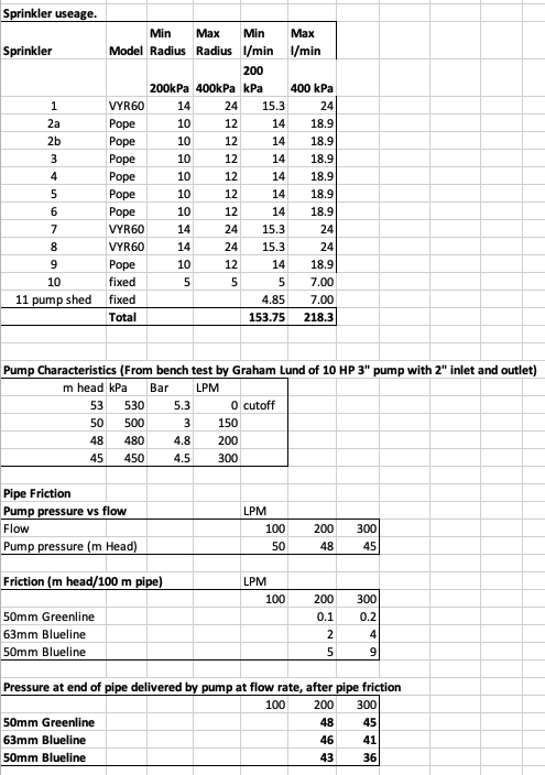
As shown above, pressure at each sprinkler, even at end of pipe, remains adequate for all the sprinkler heads, even operating with 50mm blueline, however it was essential to regulate flow at each sprinkler head using a ball valve to balance the system. Note that for reasons of an abundance of engineering caution a 63mm (external diameter) blueline pipe was utilised.
With the above choice, water flows through the 100m x63 mm (50 mm internal diameter) polypipe feeder with copper risers to sprinklers mounted on posts.
From the above we have a total low flow capacity of 2.8 hours together with a provision of 18 mins at high pressure for when the fire front is present. Overall the system will provide coverage for 3.1 hours at full flow.
Extending run-time and water service time
There are three ways of extending the time that the system can run
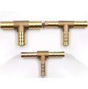
(1) install a supplementary diesel tank with a Tee junction to the pump fuel line above the fuel solenoid valve, and gravity feeding into it. A 24 l tank is available for $70. A fuel line tee for $1.18. Tanks would need to have same levels or fuel from one will overflow the other. To avoid any danger of fuel running out the provided 13 l tank, this 24 l one could simply replace it.
 |  |
(2) Utilise an automatic electrically pumped fuel top up system.
(3) To spray only intermittently in the period of ember attack.
Intermittent spray Mode
The calculations below show the outcome for an intermittent spray mode. For example, if the sprinklers were to run for 60 seconds on, then rest for 150 secs before repeating the cycle the 3.1 hours of available water would extend out by a factor of 3.2 to 10 hours.
To achieve a three-way motorised valve has been placed between the low flow system and the return to tank section of the test loop. The valve is normally open to the low flow system, but can be switched to close to that and open to the test loop return line on a cyclic basis, remotely adjustable as circumstances demand.
As a result of further development with coding the intermittent spray mode was ultimately developed to work in one of two ways:
Method 1: Valve switching - A motorised 3-way valve switches between directing water to the sprinklers and recirculating it back to the tank. This conserves water while maintaining pump operation.
Method 2: Pump cycling - When battery voltage is adequate (> 12.25V) and cycle length is >= 5 minutes, the pump is started and stopped to achieve intermittent spray. This is more water-efficient but places more stress on the pump starter.
The intermittent cycle is controlled by the autonomous module based on:
- External temperature
- Rate of temperature rise
- Ember trap activation
- Battery voltage
- Time since last ember detection
- Manual override settings
Run time in intermittent spray mode can be extended by:
- Increasing the off-time in the spray cycle (reduces average water consumption)
- Using valve switching instead of pump cycling (maintains pump readiness)
- Reducing the number of active sprinklers (requires manual valve adjustment)
- Adding gel at the final stage (increases surface protection per litre)
The table below shows the effect of different spray/pause ratios on total run time:
| Spray Time | Pause Time | Duty Cycle | Effective Run Time |
|---|---|---|---|
| 2 min | 2 min | 50% | 6 hours |
| 2 min | 4 min | 33% | 9 hours |
| 2 min | 8 min | 20% | 15 hours |
| 1 min | 4 min | 20% | 15 hours |
Note: These times assume a 30.3 kL tank starting full, low volume mode (150 L/min spray rate), and no tank refilling during operation.
Table: Summary of intermittent spray mode
The key parameters for intermittent spray operation:
| Parameter | Value | Notes |
| Tank Capacity | 30,300 L | Starting full |
| Spray Flow Rate | 150 L/min | Low volume mode |
| Continuous Run Time | 3 hours | = 30,300 / 150 / 60 |
| Intermittent 50% Duty | 6 hours | Spray 2 min, pause 2 min |
| Intermittent 33% Duty | 9 hours | Spray 2 min, pause 4 min |
| Intermittent 20% Duty | 15 hours | Spray 2 min, pause 8 min |
| Minimum Cycle Time | 5 minutes | For pump start/stop method |
| Battery Threshold | 12.25 V | Minimum for pump cycling |
Since we have a powerful battery in the pump shed (in this case a 44AH Fullriver HC44) supported by continuous charging using a sophisticated Victron charger. Experimentation shows that whilst the battery is charging the pump can be stopped and re-started with no obvious impact on the battery.
The battery is rated at 560 Cold Cranking Amps which is plenty for each cranking period of less than 4 sec. Based on 4 sec cranking with an initial surge of 400A and then 120 A in warm conditions the theoretical capacity of the battery is likely to lie in the order of 330 cranking attempts and with current performance which is requiring two cranking attempts to start that comes down to some 165 starts. However, conservative planning would reduce this to 60-120 starts.
The principle adopted therefore is to monitor the battery voltage, and provided it is above a threshold, currently set at 12.25 V, and the period off between cycles is ≥ 4 min, to start, stop and restart the pump in order to create the required intermittent spray. Once the voltage drops below the threshold the system automatically switches to the fall-back approach of leaving the pump on continously and alternating between spray and recirculating the water back to the tank. This saves water but not diesel fuel which is currently sufficient for about 6.5 hours of continous operation. :
In Autonomous mode autonomous module automatically selects the appropriate duty cycle based on:
- Detected threat level (ember traps, external temperature)
- Rate of temperature increase
- Time elapsed since last threat detection
- Available battery power
- Manual override settings from the dashboard
Footnotes
1 See Justin Leonard: "Minimum 100mm depth is adequate unless a vehicle or pile of wood or a fence is burning above the line, in which case needs to be deeper." https://bushfireresilience.org.au/wp-content/uploads/2022/03/Video-07-Sprays-2.pdf
<< Development Notes A | | Development Notes C >> |Table of Contents>