
Electronics and Control Systems
 |  |
Development History
The electronic design for ARMAC went through several iterations. In the original design the Raspberry Pi - handling the Home Assistant dashboard and MQTT server bridge between the outside world and system - and one Arduino lived in the House. That single Arduino commanded the system valves via relays by direct connection to the relay logic inputs via the multicore cable and also received and processed the sensor data on separate wires and transmitted the whole to the Raspberry Pi.. This proved electrically vulnerable to electromagnetic interference and even with hardening of various sorts components remained vulnerable, notably when the pump starter motor fired up.
In addition, in practice it was found that two Arduinos were needed to process in real time sensor inputs transmitted also to the House over the multicore cable. This was getting pretty cumbersome, data received was not very reliable, and the relays tended to have a mind of their own. And, despite a range of steps to harden the system against electromagnetic interference, including separating power from relays and more fragile components, and the use of ferrite beads, filters, etc, things remained too fragile for a system that needs to be resilient under pressure.
It also became increasingly attractive to incorporate some level of autonomous decision making into the system so that if communication with the outside world was lost, the system could still continue to respond to an increasing (or decreasing) threat. The next move was to shift an Arduino into the pump shed to make autonomous decision making possible. This it was hoped it could when necessary command the relays by wiring the logic side of the relays with two wires, each protected by a one-way rectifying diode. One wire was to come from the house on the red underground multicore cable, and the other directly from the shed Arduino. The relay control wires were biased up by connection via a 10 k Ohm resistor to 5 Volt. In the end this approach still proved inadequate - it was vulnerable to signal collision, and cable noise.
There was also a slightly more sophisticated problem. If you are going to have fairly complex decision making code, how are you to know if or not it is working? It needs testing. Initially I had the code also with test features so that it tested itself. But it is very easy for the test code to become self-verifying rather than actually testing the other parts of the code.
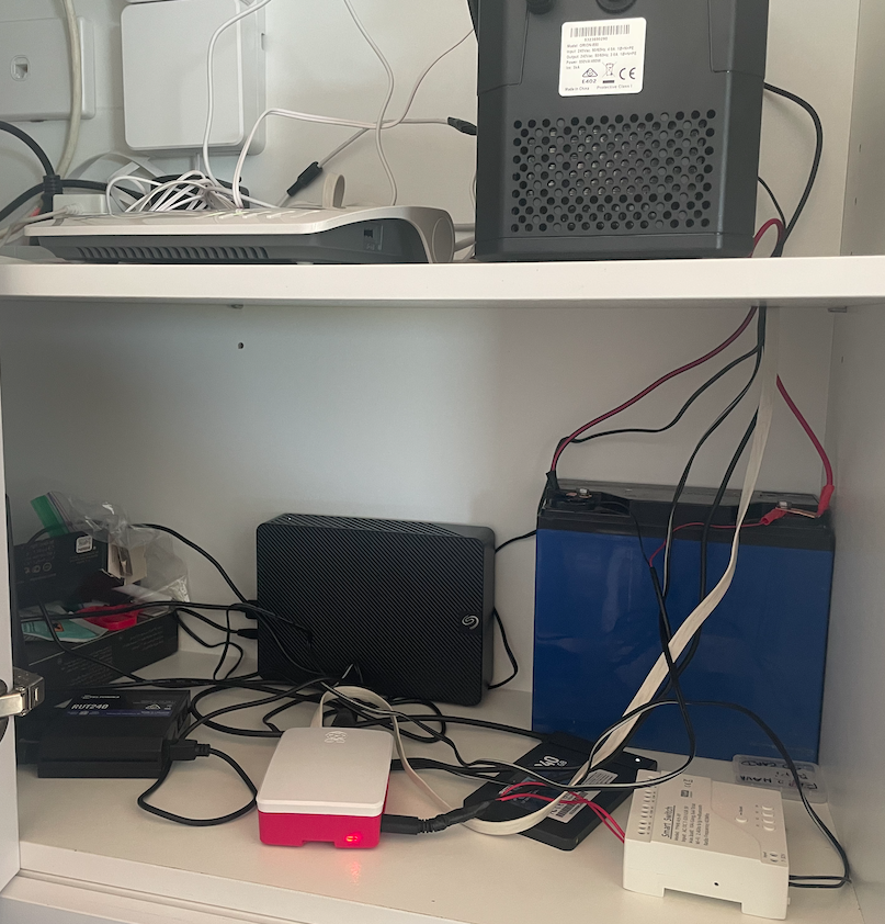
In the end I bit the bullet and decided to create the current system. This required a complete re-vamp of the system's electronic hardware and software. It introduced the current architecture of the House modules being responsible for communication with the external world, and the relays, sensor information, and autonomous decision making being carried out in the shed. The Raspberry Pi was relocated to the same place that the routers are linked to the external optical cable and all of that was supported by a large, continuously charged 12V battery. The rest was packaged into proper enclosures as modules.
As for testing, with the sensors being interrogated and their inputs interpreted by code in AR2, and the outcomes being transmitted to AR3, it became practical to simply have a test program in AR2 which could take over from the actual sensor input with simulated values, then sequentially changed along a scenario that was pre-set. This enabled one to physically switch on the test scenario and see how the rest of the system responded to the test values replacing actual sensor inputs. With this it was possible to robustly check out the faithfulness with which the system responses followed what was intended. Scenario tests could be initiated from the Arduino serial monitor, or the main sequence (scenario 1) could be initiated by pressing a small button installed on the side of Module 3.
Power between the shed and house was via a robust underground two core cable connecting the large pump battery with the a mains supported Victron 10 amp charger in the house. Properly protected by snubbers and other filters, DC Voltage Regulator modules were used to convert 12V DC to 5V DC or 24V DC as required.
NB As the notes that follow are a development log they sometimes address features of the prior stages in this. For example, there is occasional consideration of the number of wires of the multicore wire to be utilised, although ultimately all functions are addressed with the two wires of the RS485 communication system.
The Relay Module
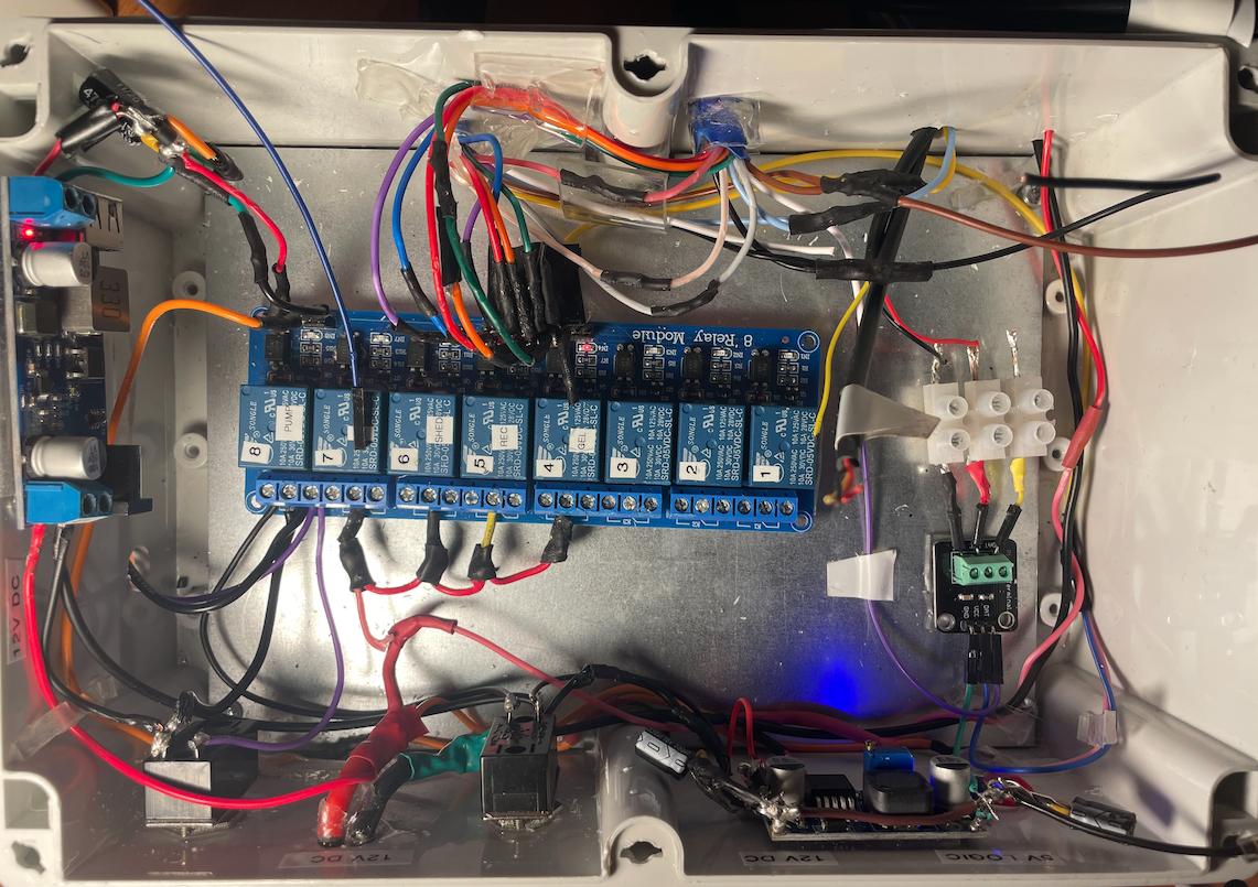
As described above this module contains the strip of Songle 5V input relays that operate the sprinkler system valves. The output side of each relay has N/C and N/O and power terminals. The relays are powered through a 12V to 5V step down module connected on the 12V side to the shed battery. The input logic side of the relays is linked to corresponding pins of Arduino AR3 by means of the blue multicore cable.
The relay module controls:
Pump Control Relays (Hardware Interlocked):
- Relay 1: Pump START (momentary)
- Relay 2: Pump STOP (momentary)
- These use Songle latching relays with hardware interlock
Valve Control Relays:
- Relay 3: Low/High pressure 3-way motorised valve
- Relay 4: Spray/Recirculation 3-way motorised valve
- Relay 5: Shed cooling solenoid valve (NC)
- Relay 6: Gel injection valve
Spare Relays:
- Relays 7-12: Reserved for future expansion
The Autonomous Module
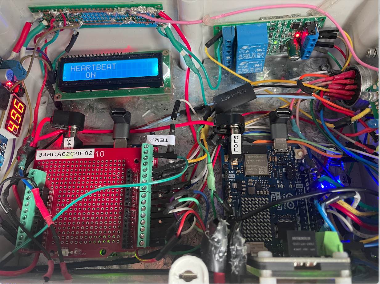
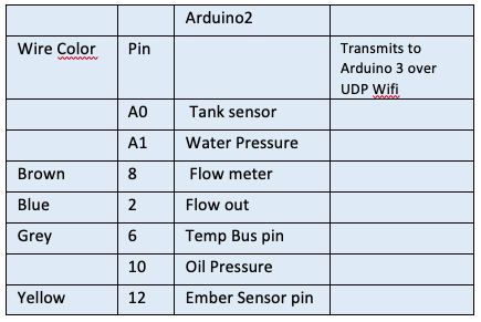
This contains the Arduino Uno R4 wifi AR2 and AR3 micro-computers. Arduino AR2 is connected to Arduino AR3 by a UNP peer-to-peer local wifi link and transmits the sensor data to A3 over this link.
The Autonomous module takes over and runs the system if it determines that effective contact has been lost with Remote Control Module. It determines this by monitoring a wire down which a regular heartbeat signal is sent from the Remote Control Module. If that fails after a pre-determined interval the Autonomous Module takes over control. It relinquishes control if the heartbeat resumes.
The tasks are complex involving timing issues, but this becomes much easier when two Arduinos (2 and 3) are assigned quite different roles.
Arduino 2 acts as the central hub for the sensor set. It receives and processes all sensor signals from outside the shed, calculates numeric values, and then transmits them every 1 second by a local UDP wifi link to Arduino 3, and by an RS485 link over two wires of the multicore underground cable to Arduino 1.
Through the its two Arduinos (Arduino 2 and 3) the Autonomous module monitors
- Arduino 1 heartbeat
- Battery level at battery in shed
- Pump oil pressure
- Pump water pressure
- Ember attack sensor
- Temperature inside and outside the shed
- Tank water level
- Water Flow through the main pipe to the sprinklers
Arduino 3 carries out the logical decision making to continue to activate valves and relays in the shed if contact is lost for any reason with the Remote Control module.
In particular if communication with the Remote Control Module, or with the internet, is lost for 5 mins the Autonomous Control Module activates. Through Arduino 3 it consults pump oil pressure and water pressure and if both are low, assumes the pump is not yet working. If pump status is off, and the states below are reached, and communication with the House Control Module is still not occurring, then the Automatic actions listed are progressively implemented. If communication with the internet and House Control Module is restored, control is handed back to the remote control dashboard. Remote launching of the Autonomous Module is achieved by a switch in the remote control panel which changes the frequency of the Arudino-1 heartbeat from 1 Hz to 2 Hz when it is desired that the Autonomous Module take over. Toggling the switch in the control panel restores the frequency to 1 Hz and restores control to the panel. The successful take-over by the Autonomous model is read in the Arduino 1 by an input heartbeat from Arduino 3 which is registered in the control panel, and all sensors remain accessible to both the Arduino 1 and through it to the remote control panel, as well as the Autonomous model via Arduino 2.
The SFS01Pump control Module (module 5)
This module was developed and is provided on a commercial basis by Small Farm Systems. It is connected to the mobile G4 network, but also by a remote stop/start wire wire 1 which activates the pump if its connection (from terminal 5 on the unit) to GND (terminal 13 on the unit) is broken. Thus the pump is activated when the N/C (normally closed) wire 1 circuit is opened. This will happen if one or more N/C switches placed in series in wire 1 are opened to set the pump running. The pump can later be turned off either by closing the circuit, or using the SMS Command STOP.
Attach: armacc_image11.jpeg
The pump control module is connected to the external G4 mobile network. A 300x300 magnesium oxide panel is set into an aperture cut into the metal shed wall immediately adjacent to the module antenna, providing transparent access to the mobile signals.
The module terminals are wired to the pump electronics as as follows:
The module is directly wired with to the pump according to the above table and the module itself is situated next to the Autonomous and Relay Modules on a set of shelves on the right wall of the shed.
Modes of operation in the Pump Shed
//
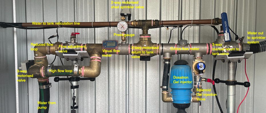
In the Relay Module, a strip of 8 Songle 5V relays is set up with with the first four logic IN pins connected via one of the multicores to corresponding Arduino 1 and 3 GPIO pins. The pump wire 1 is connected to the N/C output of relay 8 with GND connected to the common center terminal. Songle relays activate when IN is sent LOW, so the pin is normally kept at a 5V HIGH by means of a pull up connection (via a 10 k Ohm resistor) to 5V. When a LOW signal is sent via either of the Arduinos the current flows from the IN pin and the relay activates. The three terminals for a single relay being N/C on the left, common in the center, and N/O on the right. In summary, control entities from left are:
- High pressure entry from pump
- High/reduced flow branch control valve (motorized)
- Reduced flow regulating ball valve (manual)
- Visual flow meter
- Shed cooling branch ball valve (manual)
- Shed cooling motorised valve
- Intermittent control valve (motorized)
- Ports to fit gel injection as an option should it prove practical
- Online flow meter
- Test Loop ball valve (manual)
- High pressure exit to external vacuum breaker
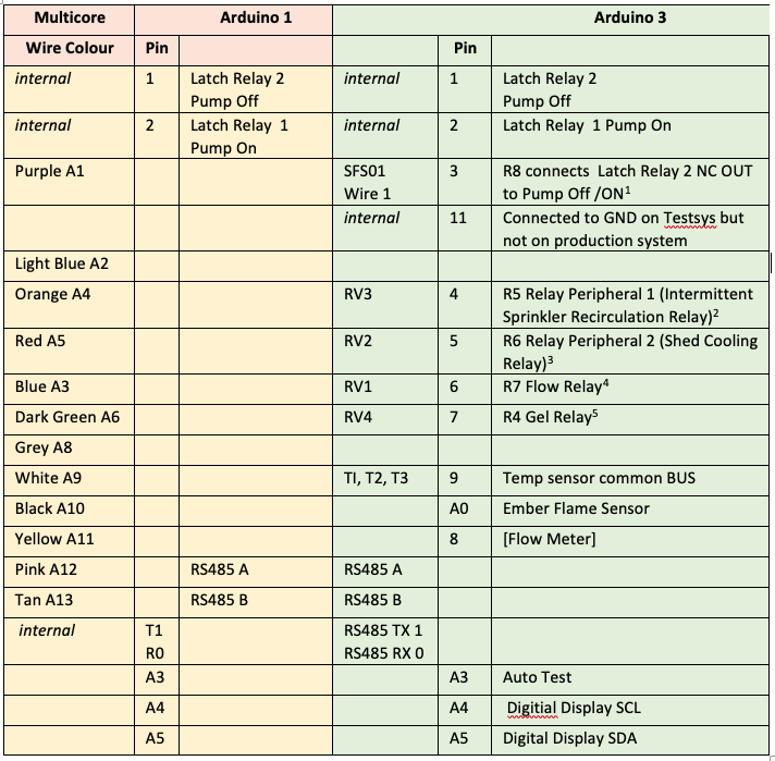
Arduino AR3 pin assignments
The GPIO pins of the Arduino connect to the relays (1-8 left to right) from the multicore cable as follows:
- Pump remote/start stop [1] on the pump module cable. This will provide a secondary way of starting the pump via the Home Assistant (HA).
- High/restricted flow motorised valve (N/High A-C see below)
- Intermittent/constant flow motorised valve (N/Constant A-B )
- Shed cooling on/off motorised valve (N/O)
- Gel injection solenoid valve (N/C)
The remaining pins are allocated to the sensors as follows
- Water Flow Rate sensor
- Shed internal temperature sensor
- External temperature sensor
- Tank water level sensor
Relay Logic
Relays and the Arduino reset
There is a problem that during an Arduino reset standard relays drift between their two states. Unfortunately this proved resistant to stabilising it with pull down resistors (whether 1kOhm, 3.3 kOhm, 4kOhm, or 10 k Ohm). The behaviour would be very worrying if it were to set the pump going during a re-set so to ensure this does not happen, two Songle latch relays are used operating in Latch Interlock mode.
Logic Table for Hardware Interlocked Songle Latch Relays (Pump Control)
This logic table outlines the behaviour of the two interlocked latch relays used to control the pump. The hardware enforces mutual exclusivity, meaning only one relay can be active (LOW) at a time where:
- relayPumpOn (R1): Controls turning the pump ON.
- relayPumpOff (R2): Controls turning the pump OFF.
- Active State: For Songle relays, LOW typically activates the relay, and HIGH deactivates it.
- Pump State: Represents whether the pump is ON or OFF.
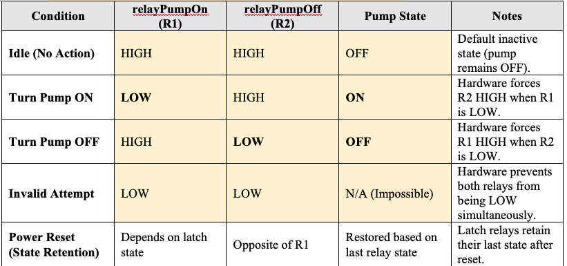
Key Hardware Behaviors:
- Mutual Exclusivity:
- When relayPumpOn is set to LOW, hardware automatically sets relayPumpOff to HIGH.
- Conversely, when relayPumpOff is set to LOW, relayPumpOn` is forced to HIGH.
- Its impossible for both relays to be LOW simultaneously.
- State Retention:
- The latch relays retain their last state even during an Arduino reset or power cycle.
- This ensures the pump remains in the correct state without additional software intervention.
- Software Control Simplification:
- No need to explicitly deactivate the opposite relay in the code.
- Simply toggling the desired relay is sufficient as the hardware ensures exclusivity.
Notes
- We can alternate the pump circuit between pump ON and pump OFF with a single switch in Home Assistant. However, the operation of the two interlocked relays requires connection to two pins of the Arduino (GPIO2 and GPIO3). However, whilst the hardware of the relays then prevents inadvertant toggling, the output of relay R1 is then sufficient to control the pump circuit.
- To further assure correct behaviour after a reset current state of the pump is written to EEPROM so that after a reset the sketch ensures the pump is set to its former state.
Relay setting programming notes
As noted the pump is started by opening the wire 1 circuit in the shed. A standard relay controls this in the shed, but this shed relay is activated from a signal from the Arduino in the house controlled through two connected latch relays, and thence through the multicore wire from the house. Thus connected to the Arduino are two SONGLE SRD SRD-05VDC-SL-C latch relays in self-locking (toggle) mode (the mode being set by a dip switch with 1000 set). The Arduino sketch is required to switch between the N/C and N/O connectors. The code requires for an ON message for the control GIOP pin to go HIGH, then delay 100, then go LOW, then delay 100, then go HIGH again. For an OFF message it requires the pin to go LOW. The relay triggers on LOW control. This signalling behaviour is needed because latching relays dont rely on continuous power to hold their position; instead, they need brief pulses to toggle between states. These must follow the following pattern:
- Initial HIGH: This step prepares the GPIO pin and relay circuit. Its a stabilization step to ensure the relay circuit detects the upcoming pulse accurately.
- LOW (Triggering Pulse): Setting the control pin LOW triggers the relay because its configured to respond to a LOW signal. This pulse changes the relay's state (from OFF to ON or vice versa, depending on its current position).
- Final HIGH: Setting the pin back to HIGH ensures the control circuit is reset and wont accidentally re-trigger the relay. This effectively "clears" the pulse, making the relay ready for the next command.
In this sequence, the delay between the transitions (HIGH to LOW and then back to HIGH) ensures that the relay has enough time to detect and act on the LOW pulse before resetting. This method is common for latching relays, as it mimics pressing and releasing a physical toggle switch.
Tank Water Level Sensor installation
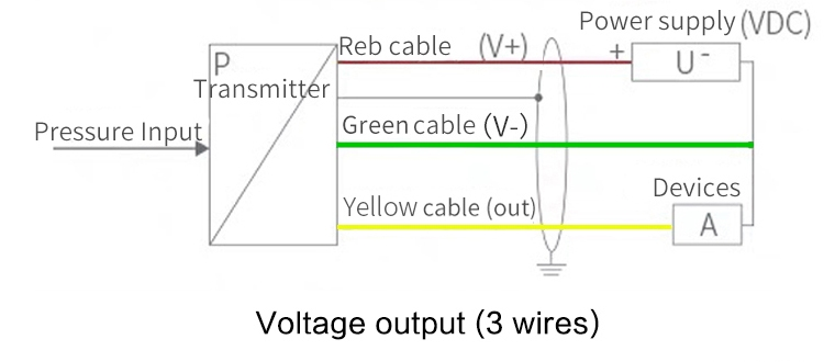
After encountering difficulties with an RS485 water depth sensor it was replaced it with a 3 wire QDY30A submersible Water Level Sensor with an SS304 probe advertised on Aliexpress. This has an 0-5V analog output which can be directed immediately to an Arduino pin, and accepts 12-24 V. Wiring is as below:
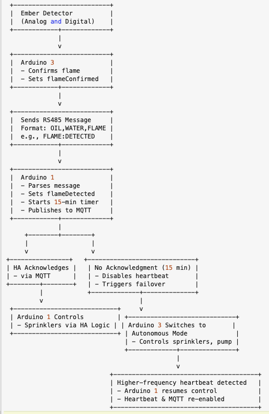
System response to Ember attack
The trigger for initial action is detection of wind-born firebrands variously referred to as cinders or ember attack. An ember attack sensor has been designed and deployed and as soon as it is activated it sends a message to Arduino 3. Arduino 3 immediately does two things:
- It begins a wetting cycle by turning the pump on on an initial reduced flow, 3 min on and 20 min off cycle.
- It communicates with Arduino 1 which initiates a series of alarm messages to the Home Assistant app. Even if the app is asleep it will be woken and trigger visual and audible alarms on each platform (ipad, iphone or computer) on which it is running. The alarms will be repeated at 5 min intervals until acknowledged from the Home Assistant dashboard or the Autonomous module has established that contact has been lost between it and the internet.
Assuming the Home Assistant dashboard is functional the system can then be manually managed it using the available sensors and video cam to select appropriate responses from anywhere in the world. In the event of communication not being made and no response from the dashboard over the next 15 min, the system will enter Autonomous mode control. However, Autonomous mode can always be switched back to the Dashboard from it.
A flow chart summarising major actions following ember attack detections is shown below:
Inter-Module Communication
Multicore red and blue cable: connections
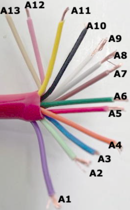 | 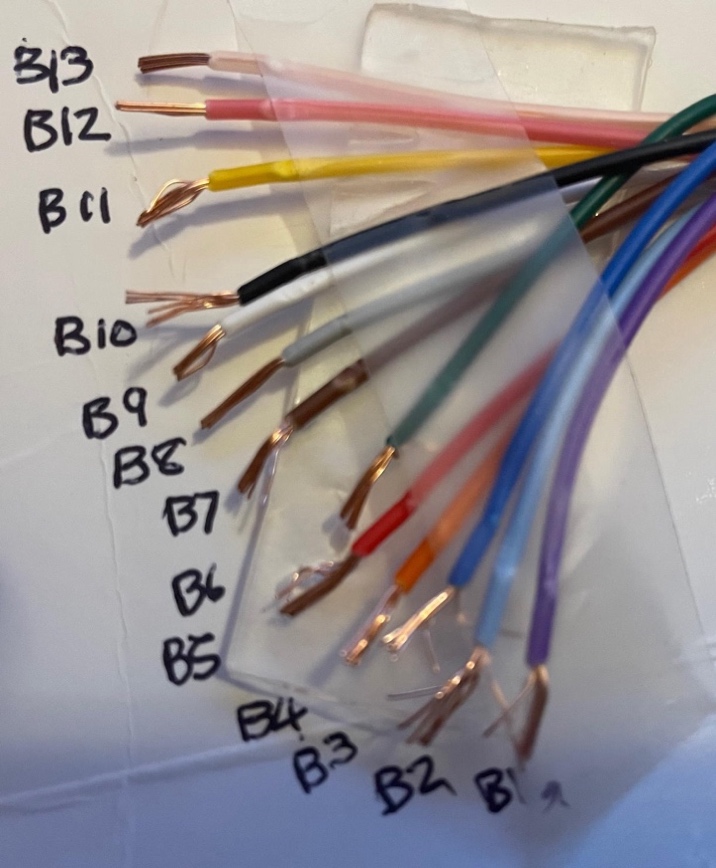 |
(Color labels used: A1 purple; A2 light blue; A3 blue; A4 orange; A5 red; A6 green; A7 brown; A8 grey; A9 white; A10 black; A11 yellow; A12 pink; A13 tan. Similar colour identifications for B1-B13, albeit with B13 more transparent than tan) The connections between the three Arduinos and this multi-core communication cable are shown in the following table.
Primary connections between Arduino pins, and relays and sensor
 |
 |
Notes
- All the Arduino modules are Arduino Uno R4 Wifi and 2 and 3 communicate as nodes on that local wifi connection. Included in those transmissions are battery voltage, tank level sensor, flow sensor, and Arduino 3 heartbeat to Arduino 2. At a later stage Arduino 2 may be programmed to take over for Arduino 3 in the event of Arduino 3 failing.
- Arduino 1 and 2 communicate remaining messages via two wires (A and B) of the multicore cable using half duplex multi-message Gravity RS485 interfaces over Multicore wire 12 (pink). Currently Arduino 2 monitors Battery Voltage (in the shed), Flow Meter Sensor, and Tank Sensor which it communicates by Wifi to Arduino 3 and by RS485 to Arduino 1. It also receives over wifi the three Temperature readings,
- Each of the above connections between AR3 pins and the relay logic ports is protected by a 1N5819 Shottky diode (with an acceptable 0.2-0.4V voltage drop) in series.
- All of the pins on the Arduino coupled as inputs to the relay strip are biased High (Off) through a 6.8 k Ohm resistor to prevent the pinout voltage drifting LOW during a reset.
- The motorised 3-way valves (RV1, RV3) are controlled with A-B and A-C selected with blue or brown wire respectively. The motorised valves must be powered for the full period that the motor is rotating the ball valve. However, they cease to draw power once the valve has reached its new correct state. Thus we can use the N/C and N/O states of the relays to achieve the necessary changes.
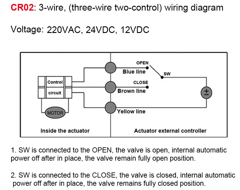 |
- Motorised 2-way (RV2) valve (see CRO2 below) for shed cooling system is similarly controlled with blue line valve is open; brown line valve is closed. See also Appendix 1.
Gravity-RS485 half duplex serial communication.
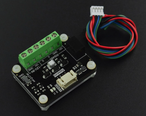 |
A and B wires (A12 Pink) and (A13 Tan) are reserved to connect the two Arduinos (1 and 3) allowing them to send multiple messages relating to different sensors and relays using a half-duplex protocol (send and receive, but not both at once). As already discussed this improvement was introduced rather late into the project to both conserve wires, but more importantly harden the electronic architecture. The RS-485 protocol uses two Gravity 485 ttl to RS-485 transcievers to connect each Arduino over the A and B wires . A terminating resistor across the two wires is switched on one of the Gravity Units to avoid signal reflection.
The Gravity DFR0845 RS-485 module typically requires two communication connections plus power VCC and GND on one side of the module: RX (Receiver Input): Connects to the R port of the Gravity module. TX (Transmitter Output): Connects to T port of the Gravity module. On the other side the A and B wires connect the two modules together.
Note. We initially tried using very cheap MAX485 transceivers but had unreliable results. So we replaced them with the slightly more expensive but robust Gravity transceivers. The MAX485 has DE (Driver Enable) and RE (Receiver Enable) connections that determine the signal direction of each message, and are typically tied together driven by a single pin on each Arduino. The tied DE and RE wires, driven by a single pin, is standard configuration, and suffices provided there is no rapid toggling between sending and receiving data adopting a simple control protocol of (both HIGH for transmit, both LOW for receive). However, the Gravity transceiver does not require a RE/DE connection. The Gravity module has automatic direction control built-in. It detects when data is being transmitted on the TX line and automatically switches to transmit mode, then returns to receive mode when idle. Currently in the sketches the D8/D12 are still reserved to a pin even though with the Gravity module they aren't actually doing anything. This is pure laziness and will be cleaned up.... one day!
Criteria for Automatic actions in the Autonomous mode
Even if all of the communication mobile net and wifi power off, if the mains power goes down, and the water mains turn off, Autonomous module provides the system with a mind of its own and its own resources. A powerful HC44 battery supplies power, water is in the tank, and a third Arduino micro computer in the shed monitors the engine oil pressure, pump water pressure, and other sensors. It is programmed to do the following (the parameters can be changed to suit): If communication is lost to wifi and the mobile net and to the house control system, and the pump is not going (as determined by oil pressure low, water pressure low, flow zero) then the system will proceed to follow a detailed set of protocols depending on the internal temperature of the pump shed (>60 deg swtiches shed cooling on) and external temperature (>70 deg switches the pump on at reduced flow and running the sprinklers intermittently (3min on, 7 min off). As temperature rises the sprinkling becomes more frequent and once the external temperature reaches 80 deg C, if the rise rate exceeds 3 deg per minute the flow is increased to high flow. Once the external temperature starts to decline the system goes back to reduced flow, then intermittent, and finally stops. The system also monitors the water level, changing its rates of water application depending on the amount of remaining water. If the water level gets very low then the system sprays fire-retardant gel before stopping the pump. Finally battery voltage is monitored and while it is good (>12.5 volt) for the longer intermittent cycles it achieves those by turning the pump off and back on, but if the voltage reduces further, the battery is conserved by leaving the pump on and turning the flow on, or alternative through a recycling valve back to the tank The specific criteria applied in the warm-up and cool-down phases, and actions taken are shown in the following table.
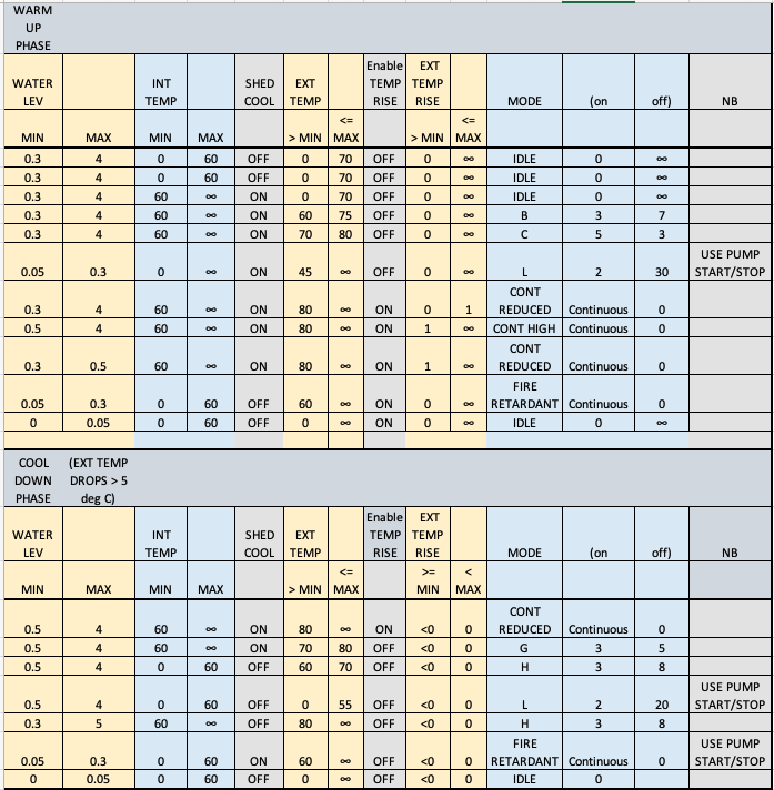 |
Note the following
- System checks oil and water pressure low before turning pump on.
- Whilst the battery voltage is > a fixed threshold, currently12.25 V, and provided pump is on for at least 5 min in each intermittent cycle, the sprinkler system will operate in intermittent mode by starting and restarting the pump with the starter motor. Once the battery voltage ≤ 12.25 V or the period on is less than 5 min, the pump will stay on and a valve will switch the flow of water to the sprinklers, and then to recirculate to the tank, for each on/off intermittent cycle. For the long intermittent cycle (2 min on, 30 min off) the pump will turn on and off as required irrespective of remaining battery voltage.
- Shed cooling is also run in intermittent mode but as follows. If the pump is off, shed cooling will occur at low flow, fed simply by gravity driven by the difference between height of water in the tank and top of the shed. Once the pump starts the shed cooling will follow the cycle of the pump until the voltage threshold is reached, and thereafter will switch on and off in synchrony with the sprinkler system.
- The end point of cooldown after the fire has passed is Mode L which handles any further ember attack by continuing to cycle either the pump on/off or recirculation valve (depending on battery state) with 2 min spraying followed by a 20 min pause. This continues until either (1) the pump runs out of fuel, or (2) water is exhausted as demonstrated by there being flow of < 1 l/min (or flow meter failure) AND low water pressure at the pump as detected by the pump pressure switch. If these two conditions are met, the pump is turned off.
Sensor Failure Fallback
A significant vulnerability to the automated system, and even manual control is the possibility that sensors key to the automated autonomous module may fail. The key sensors are those monitoring temperature and remaining water.
Temperature sensor fallback
Two external sensors are included one at a distance from the pump shed, the second with the metal sensor end only protruding through the pump shed wall, and finally the internal sensor inside the shed. Anticipating the possibility of failure the system operates as follows:
Fallback Mode Logic
The system is active under the normal autnomous module protocos when the maximum value of the three temperature sensors > 30.0 °C. When the two external temperature sensors fail fall below 30 °C indicating potential sensor failure or degraded environmental input the system utilises as a proxy for temperature the measurement by the remaining sensor inside the pump shed to which is added the difference between the last measurement of the external temperature and corresponding measurement of internal temperature at that time. If all three temperature sensors fail the system enters fallback mode. This mode enables continued operation without temperature feedback by progressing through a predefined sequence of pump control modes, driven purely by elapsed time.
Fallback Progression Sequence
Upon entering fallback, the system selects an appropriate starting point based on the last operating mode before temperatures became invalid: and then runs from the corresponding point to the end of the mode sequence (see previous table) mode B → mode C → mode CONT_REDUCED → mode CONT_HIGH → mode CONT_REDUCED → mode G → mode H → mode L
Timed Mode Transitions
At the moment 5 minutes is chosen as a fixed interval before the system advances to the next fallback stage unless already in the final state INT_L is reached after which that mode is maintained indefinitely unless a shutdown is forced due to water depletion. This short time interval in each mode is based on the premise that the most likely time for the sensors to fail is when the external temperature is already high, due to the near arrival of the fire front. The experience then (see Appendix 14 ) is that fire front passes quickly.
Shutdown Condition
If tank water level drops below 0.05 m, fallback is exited and the system transitions to MODE_IDLE to ensure water conservation and pump safety. Obviously if diesel fuel is exhausted the pump stops through its own mechanical constraints. This logic ensures a structured fallback response that maintains protective operation and gracefully degrades water usage in the absence of temperature feedback.
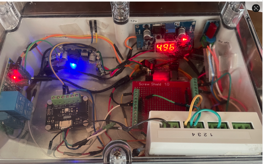
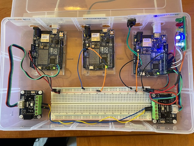
System Testing: The TestSys Module
It is important to be able to establish the autonomous modules actual performance through all likely scenarios of temperature and water level change to which it responds. This is now simply achieved by running different scenarios of sensor values in Arduino 2 (Pump Shed). On the basis of these we can check how the programmed responses in Arduino 3 (also in the Pump Shed) and in particular the resultant energising of relays proceed.
Autonomous and manual functions can be tested in the installed production system, but can also be tested in TestSys a small development module consisting of three Arduinos (AR1, AR2 and AR3) programmed as for the production system, two Gravity RS485 communication modules mirroring communication between AR3 and AR1, and 5 LEDs which light up when Arduino 3 energises corresponding valve relays. As in the production system AR2 and AR3 communicate by their own wifi UDP capabilities. For test purposes TestSys can also interact via WiFi with a test Home Assistant dashboard running either on a local computer (or here via a spare Raspberry Pi).
The TestSys module is wired with a connection between Arduino 3 pin D11 to GND, which enables the programs to determine whether they are in the Test or Production environments and choose the correct Home Assistant Dashboard to interact with, as well as make some other necessary option selections. As with the production module, a mini button switch is provided which if pressed initiates (via a command from AR3) the test scenarios in Arduino 2.
Figure. The TestSys module
Deploying TestSys at Fairhaven
TestSys is normally operated at the developer's home in Rowe St, Melbourne, where it connects via local WiFi to the Rowe St Home Assistant and MQTT broker (Raspberry Pi). However, it can also be brought to Fairhaven for integrated testing against production network conditions � for example, to verify relay command routing over real RS-485 wiring, or to test AR1/AR3 comms-path switching with the production cable run.
Deploying TestSys at Fairhaven introduces a routing problem: the Fairhaven router (FritzBox) is the gateway for local network LPNet (192.fff.fff.x), and the Rowe St broker is on a completely separate network (192.rrr.rrr.x). While the developer's Mac can reach Rowe St via Tailscale VPN, the Arduino itself is not a Tailscale node and has no route to Rowe St. A direct MQTT connection from AR1 to the Rowe St broker fails.
Solution overview: a Mac running at Fairhaven acts as an MQTT bridge, accepting connections from AR1 on LPNet and forwarding all MQTT traffic to Rowe St via Tailscale. AR1 identifies itself as TestSys hardware via a physical jumper and automatically routes its MQTT connection to the Mac bridge rather than to either RPi directly.
Hardware identification � AR1 D13 jumper
A wire strap from AR1 pin D13 to GND identifies the TestSys module to its own sketch. D13 is configured as INPUT_PULLUP at boot; if read LOW (pulled to GND by the strap), the sketch sets an internal flag JF_isTestSys = true before WiFi connects. If floating (HIGH), the sketch runs as Production. This requires no code change and no EEPROM state � the hardware configuration determines mode automatically on every boot.
The Production AR1 at Fairhaven does not have this strap, so uploading identical firmware to both boards produces the correct behaviour on each.
AR1 sketch additions
Two additions were made to the AR1 sketch to support this:
- A compile-time constant NET_BRIDGE_MQTT in config.h holds the Mac's LPNet IP address
(192.mmm.mmm.mmm � see DHCP note below).
- In setup_wifi(), after WiFi connects, the broker selection logic checks: if the connected
SSID is LPNet and JF_isTestSys is true, ACTIVE_MQTT is set to NET_BRIDGE_MQTT rather than to the local RPi. On all other SSID/hardware combinations, the normal per-network broker address is used unchanged.
The relevant config.h define:
// TestSys at Fairhaven � Mac running Mosquitto bridge to Rowe St broker. // Note: Mac's LPNet IP may change with DHCP � set a DHCP reservation on FritzBox. #define NET_BRIDGE_MQTT "192.mmm.mmm.mmm"
The Mac Mosquitto bridge
Mosquitto (the MQTT broker software) is installed on the developer's Mac via Homebrew. A bridge configuration file at /usr/local/etc/mosquitto/armac-bridge.conf directs Mosquitto to listen for connections on the local network and relay all traffic to the Rowe St broker over Tailscale:
listener 1883
allow_anonymous true

connection rowe_bridge
address RoweTailscaleMagicAddress:1883
remote_username <mqtt_user>
remote_password <mqtt_password>
topic # both 0
bridge_attempt_unsubscribe false
The bridge connects outbound to the Tailscale magic address of the Rowe St RPi on port 1883, authenticating with the standard MQTT credentials. All topics (#) are bridged in both directions � AR1 publishes reach Rowe St HA, and Rowe St HA commands reach AR1.
To start the bridge before uploading AR1 at Fairhaven, run the following command in a Mac terminal:
/usr/local/sbin/mosquitto -c /usr/local/etc/mosquitto/armac-bridge.conf -d
The -d flag runs Mosquitto as a background daemon. To confirm it is running:
pgrep -a mosquitto
To stop it:
pkill mosquitto
The bridge must be running before AR1 boots; if AR1 starts and the broker is unavailable it will retry on its normal MQTT reconnect cycle, so the bridge can also be started after AR1 and it will connect on the next attempt.
DHCP reservation
The Mac's LPNet IP address (192.mmm.mmm.mmm) is assigned by DHCP and may change if the Mac reconnects after an address lease expiry. To make it permanent, set a DHCP reservation in the FritzBox using the Mac's WiFi MAC address. This ensures NET_BRIDGE_MQTT in config.h remains valid without manual updates.
Summary: TestSys at Fairhaven checklist
- Confirm D13 is strapped to GND on TestSys AR1 (not on Production AR1)
- On the Mac, run: /usr/local/sbin/mosquitto -c /usr/local/etc/mosquitto/armac-bridge.conf -d
- Upload AR1 (and AR2/AR3 if needed) via Arduino IDE
- Connect to Rowe St Home Assistant via its Tailscale address: http://RoweTailscaleMagicAddress:8123
- AR1 serial monitor will confirm: [BOOT] Hardware mode: TESTSYS, followed by MQTT broker: 192.mmm.mmm.mmm
DHCP reservation
The Mac's LPNet IP address (192.168.178.136) is assigned by DHCP and may change if the Mac reconnects after an address lease expiry. To make it permanent, set a DHCP reservation in the FritzBox using the Mac's WiFi MAC address. This ensures NET_BRIDGE_MQTT in config.h remains valid without manual updates.
Summary: TestSys at Fairhaven checklist
- Confirm D13 is strapped to GND on TestSys AR1 (not on Production AR1)
- On the Mac, run: /usr/local/sbin/mosquitto -c /usr/local/etc/mosquitto/armac-bridge.conf -d
- Upload AR1 (and AR2/AR3 if needed) via Arduino IDE
- Connect to Rowe St Home Assistant via its Tailscale address: http://rowe-ha.tail764640.ts.net:8123
- AR1 serial monitor will confirm: [BOOT] Hardware mode: TESTSYS, and then MQTT broker: 192.168.178.136
Voltage surge circuit protection
There is significant potential for voltage surges, particularly when the pump starts or stops, or control relays activate. Steps were taken to harden the sysem against these. For fuller details see Error! Reference source not found.Error! Reference source not found.. Protection of the items attached to the multicore cable are shown diagrammatically below.
Parallel circuit protection
The Arduino 3 and 13 core cable wires are connected to corresponding sensors and relays in the pump shed. This is implemented by a wired OR logic in which the external signals from the house control modules and the autonomous in-shed module are applied in parallel to relays to activate them. Programming is arranged so that the Arudino 3 cannot be switched on save that contact is lost with Arudino 1 over the multicore cable. (This situation can be forced from a toggle switch on the remote dashboard, with Arduino 1 put back in control by toggling the Arduino 3 off). In any case, in the interests of an abundance of caution, it is it is necessary to avoid conflicts should Arduinos 1 & 3 happen to operate together. In particular it is important to avoid GPIO pin conflict where if one Arduino is outputing HIGH (5V) and the other LOW (0V) a direct short circuit could be created. To avoid this for each of the parallel relay activation wires, IN5819 Schottky diodes (with an acceptable 0.2-0.4V voltage drop) are inserted in series, supported by 10 kΩ pull-down resistors.
Arduino 1 (D2) ---->|---- Diode |
---- Relay Control Input
Arduino 2 (D3) ---->|---- Diode |
NB. Operation of the Latch Relays from Arduino 3. Arduino 3 operates with the same setup as Arduino 1, with two pins (2 and 3) controlling ON and OFF through a Songle 5V two module (2 channel) latch relay. As with Arduino 1, the modules are interlocked so if one is ON the other is always OFF (HIGH).
To achieve this pin 2 is connected to IN1 (X01)and pin 3 to IN2 (X02) with VCC to 5V and GND to GND as usual. At rest COM1 is closed, and the pump is off. The relay module are set with the jumper on L (trigger on LOW).
The Arduino sketch turnPumpOn() function pulses IN1 from HIGH to LOW for 500ms and then back to HIGH. This pulse drives the relay coils unlatching COM1 from NC1 opening the circuit. turnPumpOff() pulses IN2 (HIGH to LOW to HIGH) relatching COM1 to NC1 and restoring the circuit. This can connect with diode protection directly to close the Wire 1 circuit which turns off the pump.
In the Arduino 3 sketch this can be seen to be followed through the following C function code:
digitalWrite(relayPumpOn, LOW); // pull LOW for 500 ms → energize set coil
delay(500);
digitalWrite(relayPumpOn, HIGH); // return to HIGH (idle)
LCD DISPLAY in shed of key parameters in real time
For testing and operational assurance in the shed it is important to be able to easily monitor the system performance under the control of Arduinos 2 and 3. To assist in this in the shed Arduino 3 is equipped with a LiquidCrystal_I2C lcd two line display module which is controlled by Arduino 3 through its A4 (linked to SDA) and A5 (linked to SCL) pins. This is currently programmed to output connection to the house modules (heartbeat on/off), external temperature, water flow (l/min), current mode of operation, and state of pump and the four electronically controlled valves (high/reduced flow, recirculation, shed cooling, and gel injection) rotating through four panels each showing for 3 sec.
Protection against voltage surge and spikes
The Pump starter motor and and ignition relays can create powerful voltage spikes through the system, and the delicate computer components need protection. To shield against this multiple protective measures are applied. These are summarised in Appendix 13.
Protection of more sensitive electronic components from water spray incident.
The two Arduinos (2 and 3), buck converter power supply, Liquid Crystal display and RS485 module, were mounted in a polycarbonate sealed enclosure from Industrial Enclosures ($22 11 shipping). The enclosure was chosen because it is IP66 rated with operating temperatures 20-110 deg C, flamability only when reaching 960 deg C. Heat generated by the electronics inside is as follows: 2 Arduino R4 Wifi boards = 2 x (0.3 up to 0.8 W under Wi-Fi/MCU loads) = 1-2 W continuous Buck converter approx 0.1-0.3 W Six LEDs if half on continuously 0.12 W RS-485 transciever 0.1-0.3 W. Liquid crystal display only used in test mode. Total inside box 1.5-2.5 W of heat dissipated. Will mount electronics on an internal metal plate to spread heat. Cut two small ventilation holes on the side of the box away from the pipes (one near the top, and one near the bottom, protected with ventilation baffles.
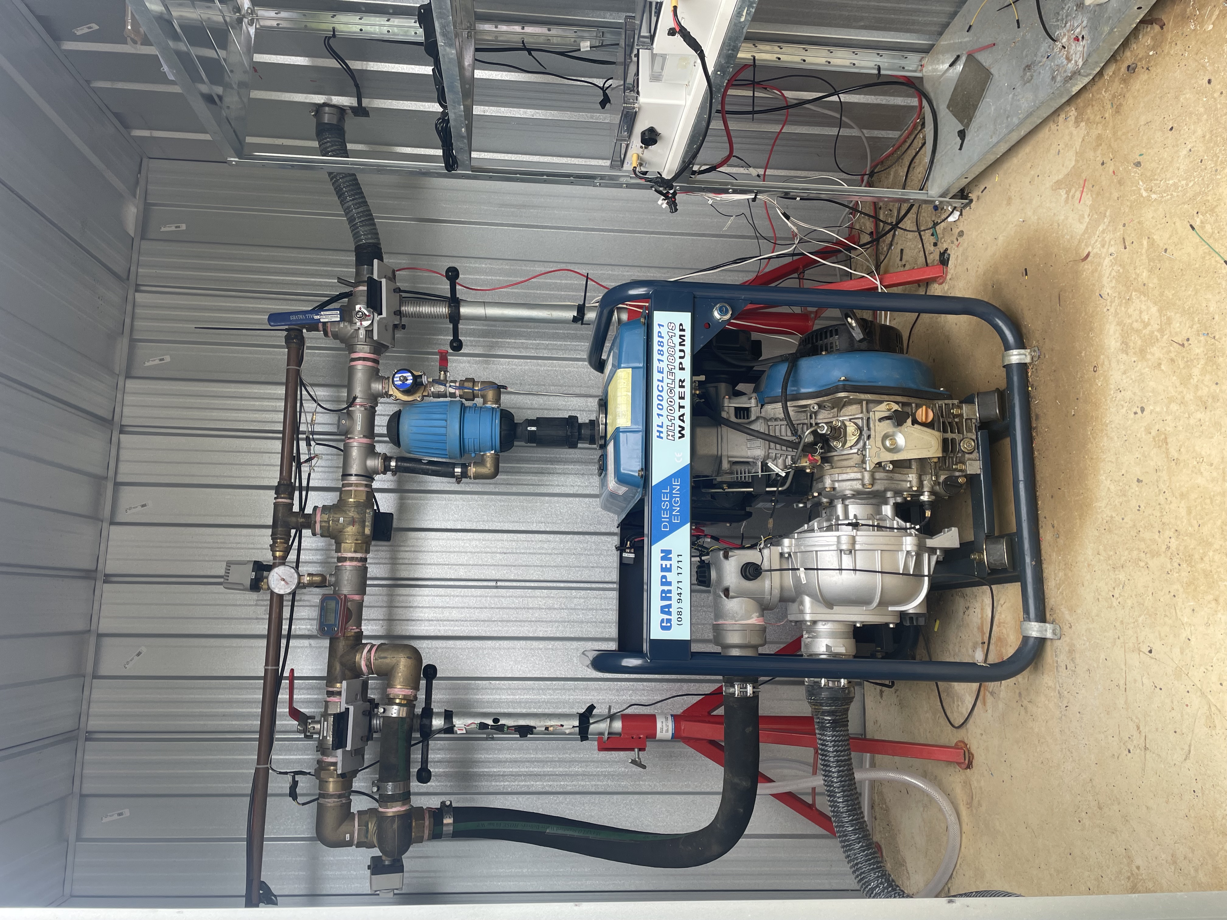
Pump Control Module setup.
The pumps direct key start is supplemented by a SFS01-V2-3G diesel pump control module. These are sold by Small Farm Services as a DIY kit for $1995. A further RF capability in the module (minus his RF wall switch) costs an additional $335. SFS will pre-wire up this module to the pump for an additional cost of $1,390. In this installation the pump was DIY wired to the supplied control box kit (including the RF capability). This requires wiring the following: 1 x oil pressure switch 1 x water pressure switch [needs to be drilled and tapped into water pump outlet] 1 x inline fuse 1 x 4G stub antenna 1 x slave relay for starter motor solenoid
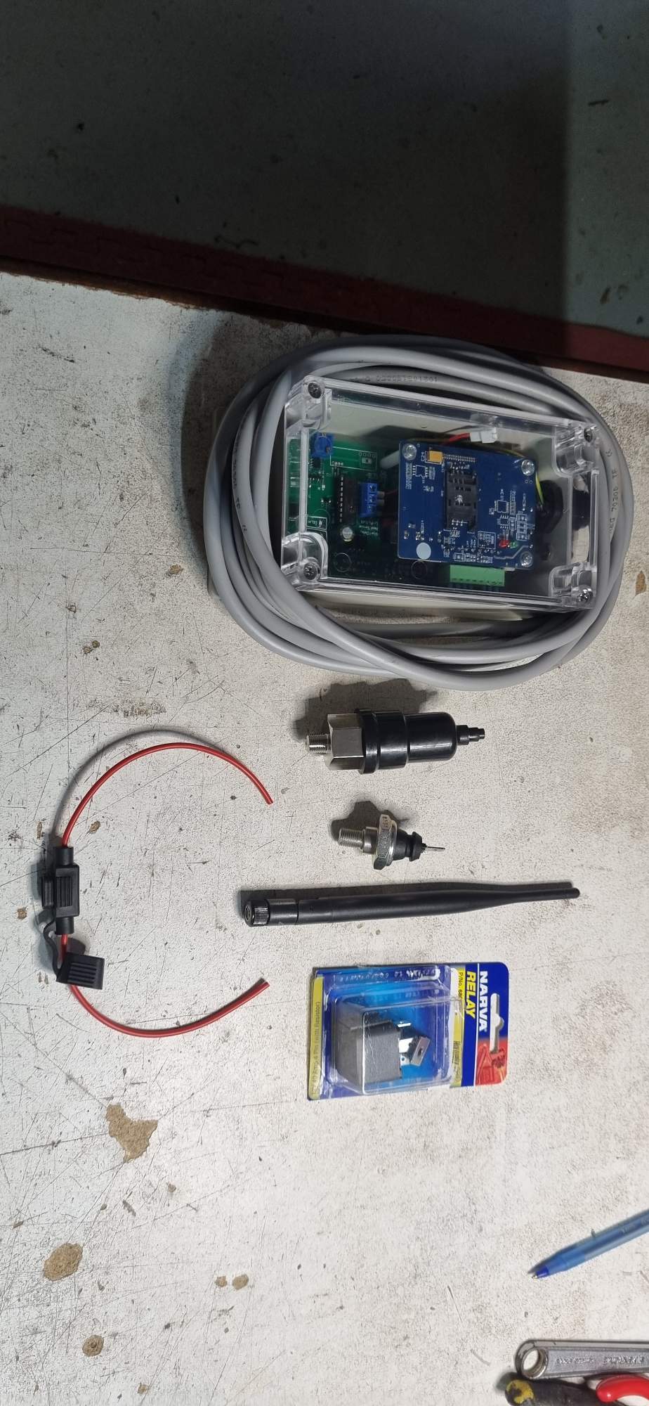
An Oil Pressure Sensor is provided and needs to be screwed into the pressurised oil gallery on the back end (pump end) of the engine. For the 188FV diesel engine a port is provided for this (31 in the expanded cylinder block diagram) and is accessed by removing the plug with an Allen key.
The port is as shown:
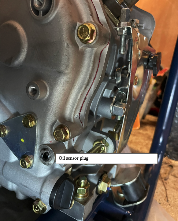
nstallation required drilling and tapping a hole in the cast iron outlet of the pump with thread 1/8 NPT to accommodate the water sensor. For drill size 0.332 inch = 8.433 mm:
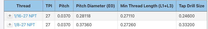
A variable speed hand electric drill was used to drill into the side of the outlet, initially with a smaller diameter 3mm cobalt drill then stepping up to the correct diameter 0.33 inch = 8.4 mm. The tap was lubed with cutting compound when tapping the thread.
Pump with oil and water pressure sensors installed
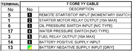
Basic harness is a 7 core YY cable which is laid up in black with white consecutive numbering.
The wiring to the control unit bus cable is as follows:
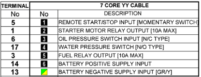
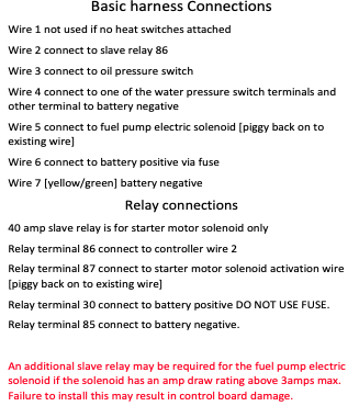
Wiring to the pump is as below:
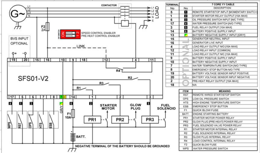
Note that Remote Start Switch RST toggles start and stop each time it opens or closes. When start is triggered it activates the starter motor through PR1 and (R1). When stop is triggered it turns off the fuel solenoid through PR3 (and R2).
{ The wired remote control of the SFS01-V2 is available through terminals 5 and 13 (using momentary N/C switch). } Terminal 13 is -ve earth. Terminal 5 (Wire number 1) is the wired remote stop/start control wire. [The manual provided contains a systematic error based on a previous now surplanted model where the pump was activated by closing a N/O circuit. As Graeme Lund confirmed the new model is the reverse configuration and is as set out below.]
{ The pump is activated when the N/C switch is opened. } Thus one or more N/C switches placed in series in wire 1 when opened will set the pump running. The pump can later be turned off using the remote capabilities.
{ For the Arduino the Songle 5V relay with pin IN pin can be connected to the corresponding Arduino GPIO2 pin. } Then for the relay connections numbered 1, 2, 3 from left as below, the pump remote start switch circuit should be connected across 2-3 which is normally closed (ie closed when IN is HIGH since Songle relays activate on LOW).
Connectors
The pump control module requires the following
- Wired remote start two pin with one pin connected to battery -ve and the other via wire 1 to terminal 5 of the controller. This switch is a N/O switch which toggles start/stop by a momentary open. Any sensor intended to trigger the pump on thus must open the wire 1 circuit.
- Charger two pin connected to corresponding terminals of the battery.
- Controller 6 pins with each pin corresponding to the numbered wires 2-6 on the controller bus.
Spade and bucket connectors were used to enable easy disconnection and reconnection for test and other purposes.
Electronically controlled Valves
The water system is controlled by the pump, manual valves, and electronically controlled motorised valves and one solenoid valve. The Arduino under instruction from either the Home Assistant dashboard or the pump shed autonomous module operates all the electronically controlled components.
To achieve this the 5V output signals of from the Arduino arriving either from the house Arduino over the multicore cable, or more directly from Arduino 3 in the pump shed (suitably protected with diodes) activate Songle relays which then switch on or off the 12V power required to turn the motorised valves, or activate the solenoid valve. 12V power is supplied from the shed battery, which is stepped down to 5V to operate the input side of the relays (and the shed Arduino 3), and for the tank level sensor stepped up to 24V. The relays:
(i) { Turn the pump on or off remotely } - on by opening momentarily RST pump control circuit (wire 1) using a normally closed relay.
(ii) { Initiate/terminate high volume mode } by switch on/off the motorised valve instituting high volume mode when the fire front is present.
(iv) { Initiate injection of fire retardant gel } in low volume mode. This requires turning off high volume mode (also turned off if water level low enough), opening the solenoid valve which controls the injection loop containing the dosatron pump which adds gel from a tub.
(vi) { Move to intermittent low volume flow } which, depending on battery state, either switches on and off the flow, or alternately allows or diverts it using a three way motorised valve to return flow to the tank.
Sensors
- Water Tank water level monitoring
For control of watering in cinder protection low volume mode, the crucial question is how much water is being used from, and remains in, the water tank. We utilised a connectivity 5 V DC input, 0 to .3.3 V DC output analog depth sensor ($54.99 from Aliexpress).
- Visual monitoring
A 360 rotatable video cam for observation of smoke levels and fire presence can be mounted on the post supporting the anti-syphon stand, and transmit remotely through house wifi or the 4G wifi modem. The cam(s) will be sacrificed in high temperature. With this in mind a 360 deg wifi integrated video cam ($17 Temu) was purchased which mounted outside the pump shed has sufficient wifi connectivity to provide a good remote picture. Input voltage is 5V DC.
- Temperature monitoring
Three DS81B20 Digital temperature sensors ($0.56 each) were utilised to measure the shed and external temperatures. Input voltage 5V DC. They come with an appropriate pull-down resistor interface for the Arduino GPIO pin interface. They can be scanned for their internal address and then addressed through a single wire common BUS. In the current setup three such sensors are utilised, one inside the shed (T1), one outside (T3), and one whose metal sensor tip protrudes through the shed wall (T2) giving some idea of the extent of cooling occurring via the sheds self spray system. In the case of this system the temperature sensors had the following addresses: T1: 28 5B 83 57 00 00 00 13 T2: 28 2E 53 57 00 00 00 3E T3: 28 11 F1 35 00 00 00 D0 I am using a net terminating resistance of 2.4 kOhm.
- Ember detection ember trap with flame IR sensing
Embers are detected by a 3 wire DV5V infrared flame detector sensor module in the 760-1100 nm wavelength ($2.83 Aliexrpess) with 80cm detection distance mounted inside a 100mm stainless steel chimney cowl) for weather protection mounted on a 100mm round end cap with 3mm rebate (cowl base $27 incl shipping Aliexpress). The base is packed with paraffin infused wood wool which is easily ignited by an ember of sufficient thermal output to endanger the house. Since this is an advance warning system it can be connected by above ground wires to the Arduino 2 and reports via RS458 from the pump shed to Remote Module and thence to Home Assistant. (It would be possible to back this with an MLX90640ESF-BAA flame detector IR camera module with a 32x24 pixel array and detection range of -40 deg C to 300 deg C over a 100 x 75 deg field of view and at a distance of up to 3 meter, available from Aliexpress for ~ $54. However at this stage it was not felt that it would add sufficient additional information to be justified). The flame sensor is connected with VCC 5V, GND, DO (digital output) to GPIO digital pin on Arduino 3 or AO to an analog pin. Both were tested and either work well, but the analog pin was utilised as being slightly more robust. The coding reports a sustained flame of at least 2 ms.
- Flow monitoring
Water flow is monitored with two Hall Effect flow meters one with direct read-out in the pump shed, and the other online. Chosen online meter is DN50 BSP Thread, with wiring Red: vcc ve, Yellow: signal out, Black Gnd -ve. Working voltage 5-18V DC
- Battery monitor
The battery is monitored both in the House Remote Control module, and in the Autonomous module using a simple voltage divider as below:
Communications reslience
The above system requires reporting over wifi, and activation of up to 8 relays. Given that the mobile network and NBN systems are vulnerable in a fire, we should have maximum control redundancy. To achieve this it is proposed to have both LTE G4 and NBN served Internet availability wherever possible.
- For the wifi systems, it will be good to have a failover system, drawing on the house wifi until such time as it is unavailable and then failing over to a G4 sim card. The router for the job appears to be the Teltonika-networks RUT240_Wireless (now surplanted by the RUT241, but having the essential features) operates at 9-30V DC and is able to accept a 4g SIM card, and failover to it. It is able to operate a wireless port in client mode use other devices WiFi for WWAN and Mesh to act as mesh network gateway or a node in a mesh network. It is also able to operate a wireless port as an access point for other wifi devices. One of these was purchased on ebay for $180.
- A possible later alternative/additional system might be to integrate a Swarm M138 satellite transciever modem (robotgear.com.au cdn.sparkfun.com). ($299) A dataplan for this costs about USD 5 per month with 750 data packets of 192 bytes per month (144kb). This would do for SMS commands (if it will transmit them) but nothing more. Swarm covers Australia. ($299 $7.70 /month) This would be impervious to the viscistudes of Optus and NBN during a fire. Its capacity to transmit SMS (which is in the voice channel) needs further investigation.
Tuya Smart Switch fall-back
A Tuya smart Wifi 4channel 4-way relay was purchased on Alibaba for $29.76. It is wifi app controlled, has 4 relays maximum current 10 A at 220V but running itself at 7-32 V DC/AC and operating in WiFi at 2.4 ghz b/n/g. It is controlled remotely by the Tuya Smart app available for iOS. The above unit has been utilised in the house control system to provide an alternative means of re-setting the microcomputers (see below) if the primary communication system they run encounters a glitch.
Antennas
Since the metal shed is almost a Gaussian cage it was necessary to either allow the G4 and house wifi signals to penetrate through a cut out section of the shed wall filled with a non-metallic material or move the antennas where they would be fire vulnerable to the outside of the shed. In the end it was decided to insert a 300x300 magnesium oxide window in the shed wall next to the pump control unit, which was sufficient for it to communicate with the G4 mobile system. However, the main wifi dependent electronic systems were installed in the house with an underground 13 core cable communicating between them and the pump shed relays and sensors.
Electronics integration through coupled Arduino-Raspberry Pi
After considerable investigation (and learning C and a host of other things such as Docker and MQTT) It was decided to integrate all the read-outs and controls for the system into one panel. The choice was to use an Arduino coupled to a Raspberry pi micro computer (running Linux). The Arduino is perfect for input of sensors and activation of relays and motors. It is also easy to incorporate into its program the intermittent requirement for the low-pressure intermittent mode, also switchable and dileable.The Raspberry Pi is well suited to running Home Assistant which has excellent integration and display characteristics. A development of the prototype and the control dashboard panel (using available sensors) is shown below. Arduino1 with multicore cable running with Home Assistant on Raspberry Pi.
Currently it is intended to retain the other components in parallel with the above to add resilience through multiple redundancy. This includes the pump module which can be controlled by sms messages.
House-based Electronics Control Sub-system
The electronics split into the main control sub-system, situated in a cabinet in the house, and an ancilliary system in the pump shed. This arrangement puts the main control sub-system in excellent contact with the house Wifi and mobile G4 system. Two cables run underground to the pump shed. The first is a 13 core multicore irrigation solenoid control cable. The second is a 12V power cable that linking the Pump battery ve with the charger ve and backup battery ve in the electronics cabinet. Care is taken that all systems share a common earth with the -ve terminal of the battery. The ve cable needed to have sufficient capacity to ensure there is no significant drop in voltage between Bat on the SFS01-v3-RF control module and the pump battery ve terminal.
The ve cable t also needs to be able to carry the Victron Blue Smart IP65 Charger 10 A current. For a 12 V system with a voltage drop limited to 2-3% over 10 meter (round trip 20 m) requires a cable of less than 0.0018 Ohm/m. From wire resistance tables 14 AWG or thicker (ie smaller AWG) meets this requirement. 10 AWG would seem ideal.
Battery Cable
AWG 10 corresponds to a 2.05 (solid) or 2.5-3 mm diameter (stranded) copper cable. 10 m of silicone insulated 10AWG 2 pin 10m is available for $49.65 (AWG 10) or 6mm (10AWG) cut to length $6.30 per meter. 12m = $75.60 $19.69 shipping = $95.29
Multicore Cable
The provided multicore cable to the pump has 7 1.8mm (ie AWG 13) copper wires. Battery ve and battery negative (wires GR/Y and 6) are supplied in a separate underground charging cable. With a resistance of -21.7 mΩ/metre per conductor the 10 m cable has a total resistance of the go and return cable of 0.434 Ω which is negligible. (For example, for a standard RS485 module with a termination resistor of 120 Ω the voltage drop would be 12.6 mV which is negligible against the RS485 standard requirement of �200 mV differential at the receiver to register a valid logic level.)
Initially the following cores were required: Relays SFS-01 Remote Start switch remotely from Arduino pin Starter Motor Relay Output Valve control: High/Low Flow Motor Valve Intemittent Motor Valve Shed cooling control Motor Valve Gel injection solenoid. Sensors Shed internal temperature External temperature Water Flow Rate Water level in tank (2 cores) Oil Pressure Sensor Water Pressure Switch Total cores: = 12 Polypropylene Toro 13 core 0.5mm = $51.72 was chosen
However in the later design all of the sensors transmitted directly into AR2 in the shed, whilst the valve relays were directly operated by AR3 also in the shed. Only two wires were required for communication by RS485 to the house.
Battery.
A battery is required in case of mains power failure during a fire and for routine diesel start. The N26 6-FM-22 12 V 22 AH battery supplied with the pump was replaced with a Fullriver HC44 battery with the N26 being relegated to supplying backup power to the house router. The Victron Blue Smart IP65 Charger has good functions and comes with an app that enables you to check the battery from anywhere within bluetooth range. In relation to this it was necessary to either utilise a 240 volt connection to the pump shed via an extension lead from the side deck, or more safely, extend the charging wires from the charger. A potentially suitable Battery charging STP-2 16 AWG (1.291 mm copper wire; resistance 13.2 ohm per 1000 m = resistance of 0.1 ohm over the 8 meter cable ) was available from Aliexpress for $14.63 and utilised. In relation to this account was taken that the trickle charge 12V Victron Charger charges at typically 2-3 Amp so the voltage loss is 0.3 Volt over the 8 meter cable. That is trivial given the charger operates between 14.4-14.7 Volt.
Motorised 3-way (and 2-way on/off) valves.
The motorised 3-way valves are available for $218 on Aliexpress (Acarps Hardware Store) and are described in Appendix 12. They can be controlled either to straight through or diversion through the common vertical T leg. Maximum operating temperature is 95 deg C. They draw 6W of power when the motor is running (for about 5-15 sec.) but otherwise stay locked in either position without any power draw. In this sense they are superior to solenoid valves.
The motor control consists of a yellow neutral earth wire, a brown wire (valve normally closed to cross flow when connected to 12V ve ie flow is at right angles to cross flow up the tail of the Tee), and a blue wire (valve normally open to cross flow when connected to 12V ve). The 2-way valve (used in the shed cooling subs system) operates according to the same wiring, but the Tee tail is closed off so that flow is either ON or OFF.
Switching the Valves using a single Songle 2-way relay
The motorised valves are operated as above, in a normally A-B (water straight through) mode when relay is open and then in an A-C (water through the Tee tail) when the relay is closed, as required. This can be achieved with a single control wire to a normal Songle 2-way relay. In normally closed state (power off).. When relay is OPEN (OFF )common and 3 are connected (yellow and brown) giving water straight through. When relay is CLOSED (ON) common and 1 (yellow and blue) are connected and this gives the A-C T-tail mode.
Programming the microcomputers
The three Arduinos require separate programming, which is done in the Arduino C language. Despite a long history of coding (over 58 years) the C language was new but assistance was provided through ChatGPT and DeepSeek which mostly cut back both programming and debugging time, although not without creating some wild goose chases along the way.
The sketches themselves may be made available on this site.
<< Development Notes B | | Appendices >> |Table of Contents>