
On command, ARMAC injects Barricade fire-blocking gel into the DN50 delivery line at a controlled ~1.4%, without ever dropping sprinkler flow below the 120 L/min the system needs. The final design uses no booster pump -- it is driven entirely by the pressure drop created by the existing manual throttle tap which sets the Reduced Flow capability.
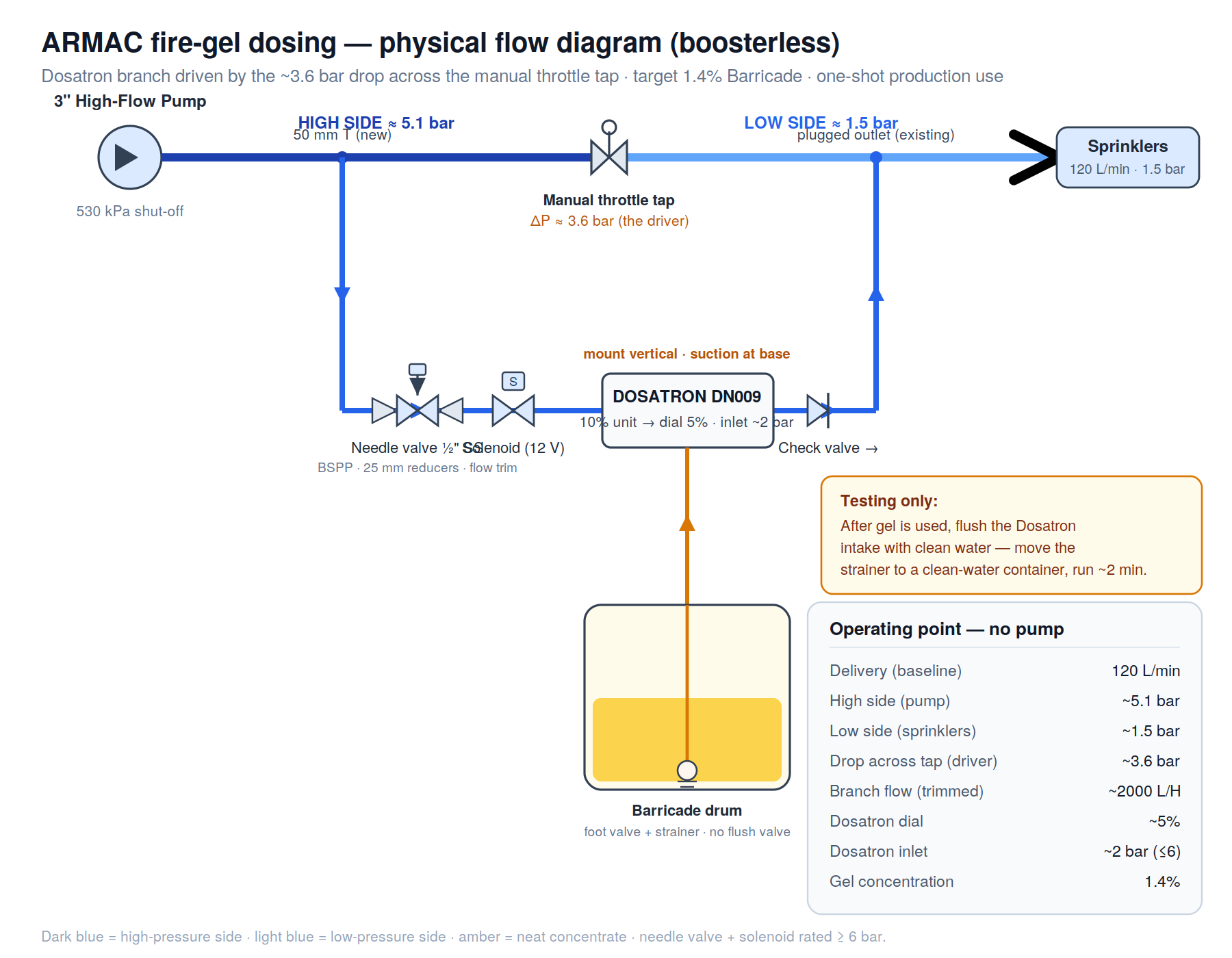
Fire-gel dosing -- physical flow diagram
Principle
A Dosatron water-driven proportional injector is plumbed with its intake directly connected to the outlet of the diesel pump, and its outlet connected after the manual low flow restriction needle valve (a "high-low pressure branch": that is, it takes water from the ~5.1 bar high side (a new 50 mm T at the pump discharge), meters neat Barricade in fixed proportion to the water passing through it (dial-set), and returns the dosed water to the ~1.5 bar low side (an existing plugged 50 mm outlet). The ~3.6 bar drop across the tap drives the branch -- about seven times the ~0.5 bar the injector needs. A 12mm needle valve (capable of fine adjustment) trims branch flow, and a solenoid valve switches dosing on or off.
Note that after testing it will be important to flush the Dosatron intake with fresh water once the test gel has been dispensed.
Two properties make it robust:
- Concentration is set by the dial, not by flow measurement -- it self-corrects against pressure and flow drift.
- The branch is a parallel path around the tap, so opening it can only raise total delivery, never drop it below the 120 L/min floor.
Operating point
| Quantity | Value |
|---|---|
| Delivery (baseline / during dosing) | 120 L/min floor / ~130-150 L/min |
| High side (pump) pressure | ~5.1 bar |
| Low side (sprinkler) pressure | ~1.5 bar |
| Drop across tap (the driver) | ~3.6 bar |
| Branch flow (gate valve-trimmed) | ~2000 L/H |
| Dosatron (Huiji DN009) dial | ~5% |
| Dosatron inlet | ~2 bar (ceiling 6 bar) |
| Gel concentration | 1.4% |
| Added pump / booster | none |
Status
Design frozen for the physical build. The pressure figures rest on a measured pump curve plus the sprinkler square law; the throttle flow reduction is confirmed by lookup once measured -- see Throttle Pressure-Drop Tables. Control logic (solenoid + 3-way, arm/dose/flush/disarm) is to be ported into the AR3 Arduino code and validated on TestSys.
Plumbing dimensions
The branch line itself runs at 25 mm (1″) — that's the pipe (or 1″ pressure hose) tapping off the DN50 main, running to and from the needle valve/solenoid/Dosatron. This was sized for the branch flow (~33 L/min → ~1.13 m/s velocity), not for the valve. The needle valve is ½″ SS304 BSPP — chosen for valve behaviour (it throttles well against the ~3.6 bar drop at that flow without being twitchy near-shut), not because the line is ½″. The Dosatron ports are also 25 mm (G1″/BSPP-ish, effectively matching the 25 mm line).
The plumbing sequence is:
Dosatron Inlet side: 50mm Tee with 20 mm F outlet, → nipple (20mm M- 15 mm M ½″) → needle valve → nipple (15mm M- 25mm M) to 25 mm → solenoid → 25 mm → 25 mm ss Ball Valve → 25mm M Hose Barb (with ss pressure clip); → 25mm hose; → 25mm M Hose Barb (with ss pressure clip); → 25mm Barrel Union → 25mm M Dosatron inlet.
Dosatron Outlet side: Dosatron 25 mm M outlet → 25mm F-F Elbow; → 25 mm M-M Hose barb → 25 mm rubber hose (with ss pressure clip) → 25mm M-M brass hosebarb (with ss pressure clip) → 25mm check valve; 25mm M - M 32mm nipple; → F 32 mm inlet port of 50mm feeder pipe Tee junction.
A composite image of the planned plumbing is below.
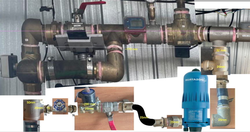
Revised plumbing plan
Since a 2" F x 3/4" F x 2" F stainless steel tee was on hand and there was no significant pressure or flow loss from doing so the tee was utilised with a 3/4" M to 1" F BSP expander - see below for Claude AI (Sonnet 5 High) calculation.
New required parts
- nipple (20mm M- 15 mm M ½″) [to needle valve]
- nipple (15mm M- 25mm M) [from needle valve]
- 3 x 25mm M brass hosebarbs
Coding requirements
The coding must require that the flow valve is turned to reduced flow, and the normally closed solenoid valve activated open to flow in order to start gel injection. Initial experimentation with flow rates will be required to ascertain the correct settings for around 1.4% dilution.
Branch Tee Outlet — 3/4" to 1" Reduction Check
The gel-injection branch tee has a 3/4" (F) outlet rather than the 1" (25 mm) used for the rest of the branch. A 3/4" M → 1" F expander bush restores the branch to its designed 25 mm bore immediately downstream of the tee. This note checks that the momentary 3/4" restriction at the tee outlet does not affect the design.
Velocity through the 3/4" bore
Target branch flow: Q = 2000 L/H = 33 L/min = 5.55 × 10⁻⁴ m³/s
Actual internal bore of made-up 3/4" BSP pipe (not the oversized thread-relief socket): d ≈ 21 mm = 0.021 m
Cross-sectional area: A = π(d/2)² = π × (0.0105)² ≈ 3.46 × 10⁻⁴ m²
Velocity: v = Q / A = (5.55 × 10⁻⁴) / (3.46 × 10⁻⁴) ≈ 1.6 m/s
For comparison, the 25 mm (1") branch itself runs at ≈ 1.13 m/s at the same flow — the 3/4" stub runs a little faster but stays well inside the normal 1–3 m/s working range for an intermittent branch like this.
Pressure loss at the fitting
A short contraction/expansion (tee outlet + reducing bush) costs roughly one velocity head:
h_L = K × v² / (2g)
Taking K ≈ 1.0–1.5 (typical minor-loss coefficient for a sudden contraction/coupling of this kind):
h_L ≈ (1.0 to 1.5) × (1.6)² / (2 × 9.81) ≈ 0.13–0.20 m of head
Converting to pressure (1 bar ≈ 10.2 m of water head):
ΔP ≈ 0.01–0.02 bar
In context
| Budget item | Value |
| Pressure available across throttle tap | ≈ 3.6 bar |
| Needle valve drop (by design) | ≈ 1.6 bar (down to ~2 bar Dosatron inlet) |
| Headroom to 6 bar Dosatron ceiling | ≈ 4 bar |
| Loss at 3/4" tee outlet + expander | ≈ 0.01–0.02 bar |
The fitting loss is roughly two orders of magnitude smaller than the available pressure budget, so it has no material effect on the design. Any small discrepancy it introduces is absorbed automatically at commissioning, since the needle valve is trimmed by the bucket method to hit the ~33 L/min target flow directly, rather than relying on a calculated setting.
Needle valve — effect on Dosatron pressure and concentration.
The branch has a fixed pressure budget of ~3.6 bar between the high tap (~5.1 bar) and the low-side return (~1.5 bar), shared in series across the needle valve, the Dosatron, and the check valve. The needle valve sets the Dosatron's inlet pressure by how much of that budget it absorbs first: closing it absorbs more and lowers the inlet, opening it absorbs less and raises the inlet. This is not an independent control of pressure and flow — it is one knob with a single effect expressed two ways, since opening the valve simultaneously raises branch flow and the head that flow costs across the Dosatron. Crucially, the metered concentration is unaffected. As a volumetric proportioner, the Dosatron draws its dial-set fraction per unit of throughput regardless of where the inlet sits within its 0.2–6 bar envelope, so pressure-across-it and dose ratio are decoupled by design: the needle valve moves the operating point along the pressure axis while the ratio stays flat along it. The delivered concentration therefore depends on the dial (the ratio) and the branch/total flow blend (how much of delivery passed through the branch to be dosed), not on the needle valve's effect on pressure. Finally, no needle-valve setting can over-pressure the injector: the inlet's maximum, with the valve wide open absorbing nothing, is the full ~5.1 bar high-tap pressure — still safely under the 6 bar ceiling — so there is margin at both ends of its travel.
Background
This is the third iteration of the gel-dosing design. Earlier work explored full-flow Dosatrons (too expensive) and a two-branch approach with a Bringsmart 12V inline booster pump to overcome the 4.5 bar system back-pressure. The boosterless design -- exploiting the ~3.6 bar drop already present across the existing manual throttle tap -- proved simpler, cheaper, and more reliable. See Gel Injection System for the earlier design history and the alternatives that were considered.
ARMAC DevNotes · pages: Overview · Design & Calculations · Throttle Pressure-Drop Tables · Build & Commissioning · Calibration