
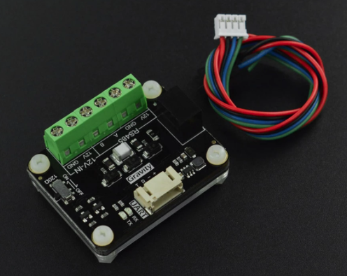
Gravity RS-485 transceiver (click to enlarge)
The system employs several distinct communication protocols, each selected specifically for its role in the overall architecture. Understanding why each protocol was chosen and how they work together reveals much about the design.
NB: For current pin assignments refer Current Pin Allocations
MQTT, running between Module 1 and Module 2, provides the interface between Home Assistant and Arduino AR1. This protocol's publish-subscribe model with retained messages and quality-of-service guarantees makes it ideal for dashboard control, where state persistence across disconnections and guaranteed delivery of critical commands are essential. The MQTT broker running in a Docker container in the Raspberry Pi maintains the authoritative state of all controllable elements, ensuring that reconnecting clients immediately receive current system status. Topics are organized hierarchically, with pump control under home/pump/inTopic, peripheral states under home/peripheral1/set through home/peripheral4/set, and sensor readings published to home/sensor/ topics. This organization allows Home Assistant automations to subscribe to specific state changes and respond accordingly.
RS-485, linking Module 2 and Module 4 over the multicore cable, was chosen for its exceptional noise immunity and reliability over extended cable runs. The differential signaling inherent to RS-485 makes it highly resistant to electromagnetic interference from the diesel pump motor and electrical noise in the pump shed environment. The implementation uses framed messages with checksum protection and explicit acknowledgment of critical commands. Every frame follows the format <PAYLOAD|CHECKSUM>. The checksum is a CRC-8 (polynomial 0x07) of the payload, written as two hexadecimal characters; unlike a simple XOR of the payload bytes, it catches common errors such as two flipped bits or swapped characters. Command frames additionally include sequence numbers from 0 to 15 that roll over, allowing the receiving end to detect and acknowledge each unique command while ignoring duplicates that might result from retry logic. How the checksum is used is described under Message checking below.
The RS-485 protocol defines several message types, each serving specific purposes. Command frames beginning with CMD: contain pump and peripheral relay states along with a sequence number and LOCK status. Status frames beginning with STAT: provide relay mirror states, heartbeat status, Home Assistant automation flags and, when AR1 has one, the battery voltage (BAT:), without commanding pump state changes. Configuration frames beginning with CFG: transmit manual intermittent timing parameters from Home Assistant to AR3. The heartbeat travels as a field (HB:1) in AR1's status frames, sent every 5 seconds, indicating that manual control is active; AR3 sends a separate HB:0 frame when it takes control itself (for example when the shed test button is pressed). Telemetry frames flow from AR3 to AR1, containing all sensor readings, current relay states, autonomous mode and phase information, FSMODE status (0 = REMOTE, 1 = AUTONOMOUS), and system ready status. Since the system is battery powered, power interruptions are operator initiated. Given this, at AR1 the A wire is routed through a RS485 bus connection switch mounted on the external module wall. With this in place the protocol to protect the Gravity unit is for the connection switch to be switched off (isolation on) prior to powering down the module, and switched back on only after power has been reinstated. To further provide some protection against a voltage surge in the event the unit is not isolated when power is switched on or off 47 Ohm resistors are put in series with both the A and B wires at the AR1 end. This is well within tolerance at 9,600 baud which is the speed at which the system communication is configured.
Beyond the hardware protection, the firmware implements three layers of software protection for the bus. First, AR1 enforces a strict transmit window: it never drives the bus spontaneously, but only transmits between 5 ms and 0.5 s after the end of an AR3 telemetry frame (timed from frames on the link it is currently using). The 5 ms guard delay allows the Gravity module's direction-switching circuitry to settle. Only one frame is dispatched per window, with CMD frames taking priority over STAT and CFG frames. A 400 ms freeze additionally prevents rapid pump direction reversals that would otherwise cause a burst of CMD retries on the bus. This ensures the two nodes never drive simultaneously — the primary failure mode for auto-direction transceivers. Second, AR1 withholds all relay CMD frames until AR3 has been confirmed alive by receipt of at least one telemetry frame containing sensor data (the ar3Ready gate). This prevents a burst of commands into a potentially unresponsive bus at startup or after a path switch. When ar3Ready transitions to true, AR1 immediately syncs current relay state so no command is permanently lost during the detection window. Third, when AR3 is operating in AUTONOMOUS mode it owns its own relays and must not accept relay commands from AR1. Simply ignoring CMD frames would cause AR1's retry logic to retransmit repeatedly, generating unnecessary bus traffic. Instead, AR3 ACKs every CMD frame even in AUTONOMOUS mode — satisfying the retry arbiter and quiescing the bus — but does not apply the relay or pump fields to its outputs.
SoftwareSerial Backup Communications between Modules 2 and 4, is a second (redundant route) linking Module 2 and Module 4 over spare wire pairs in the existing multicore cable, and was added to prevent a fault in which the RS-485 transceiver IC on AR1 could fail, silently severing communication while the rest of the system remained operational. The backup path uses Arduino's SoftwareSerial library on dedicated pins - AR1 transmits on A4 and receives on A5; AR3 transmits on A1 and receives on A2, cross-connected (AR1 A4 to AR3 A2, AR3 A1 to AR1 A5; see Current Pin Allocations) - forming a direct serial link that is entirely independent of the RS-485 transceiver hardware. Unlike RS-485 it uses one wire in each direction, so both ends can transmit at the same time.
The backup path carries the identical framed protocol used on the primary RS-485 link, including the same <PAYLOAD|CHECKSUM> frame format, CRC-8 checksum, sequence numbers, and acknowledgment logic. No protocol translation is required: AR3 processes frames from both paths through the same handler, and AR1 sends its command, status, configuration and heartbeat frames only on whichever path is currently active.
AR1 monitors the primary RS-485 path continuously and switches automatically to the backup after 15 seconds without telemetry. AR3 switches on its end of the backup link after 10 seconds of RS-485 silence and off again when RS-485 traffic returns: the SoftwareSerial receiver uses an interrupt that disturbs AR3's WiFi link to AR2, so it is only enabled when needed. While it is enabled, AR3 sends its telemetry and acknowledgments on both paths, which lets AR1 detect when RS-485 recovers. AR1 returns to the primary path only after RS-485 telemetry has been steady (no gap of 5 seconds or more) for 60 seconds, so an intermittent RS-485 wire cannot make it flap between the two links. The ar3Ready gate is re-armed on every path switch, requiring fresh telemetry confirmation from AR3 before relay commands are permitted on the new path. A dashboard test hook - the AR3 Comms Path Force control in Home Assistant - allows the operator to force either path without physically disconnecting cables. Forcing is a software switch only: the RS-485 wires stay connected. A force ends by itself after 30 minutes (3 minutes on TestSys), so it cannot be left on by mistake, and AR1 reports the path setting it is actually using, which the dashboard shows beside the control. If the path in use goes silent while forced, AR1 still raises the comms alert. Note that if the control already shows BACKUP (for example after AR1 has restarted, which clears the force), selecting BACKUP again sends nothing - select AUTO first. Home Assistant sends an email when the backup path becomes active in normal operation (at most once every 15 minutes) and, at Fairhaven, an SMS (at most once a day, with a link to acknowledge it).
Data age. Every 30 seconds AR1 reports how long it is since it last used telemetry from AR3, on whichever path is in use. If this passes 60 seconds, or AR1 stops reporting it, the dashboard shows No data from shed and, if switched on, the No data from shed alert is sent. This catches any break in the chain from the shed to the house, whatever its cause; the readings on the dashboard are then the last ones received.
AR2 live. AR3 also tells AR1 whether it is still receiving AR2's readings (within 25 seconds) and how old they are, and AR1 passes this on to Home Assistant. The last readings stay on the dashboard, with AR2 live showing whether they are current.
Receiving on the backup path. The UNO R4's SoftwareSerial receiver sometimes holds back the last one or two characters of a message until the next message starts to arrive, about 2 seconds later. It switches between this and normal behaviour unpredictably. AR1 therefore accepts a backup message once the line has been quiet for 0.5 seconds if its checksum already verifies (only the closing '>' was held back), and otherwise waits up to 2.5 seconds for the held-back characters. Because AR1's transmit window is timed from AR3's messages, a run of late messages could stop AR1 sending; since the backup link can carry both directions at once, AR1 sends anyway if it has sent nothing for 4 seconds. In a 30-minute forced-backup test 99% of AR3's messages were received intact (the rest were damaged in transit and showed as checksum errors), every message from AR1 reached AR3, and all commands from Home Assistant were carried out.
The SoftwareSerial backup path runs AR1 pin A4 (TX) to AR3 pin A2 (RX), and AR3 pin A1 (TX) to AR1 pin A5 (RX), with no RS-485 transceiver in the signal path. To protect against the unpowered-node fault condition — where a powered Arduino's TX pin forward-biases the protection diodes on the unpowered Arduino's RX pin — a 300 Ω series resistor can be placed on each TX line (AR1 A4, AR3 A1). TestSys, with its short wires, has none; whether they are fitted on the 10 m cable at Fairhaven is still to be confirmed. This limits fault current to (3.3 − 0.7) / 300 ≈ 8.7 mA, within the RA4M1 GPIO diode rating, while remaining transparent at 9600 baud where the 104 µs bit period dwarfs the RC rise time.
- Every message between AR1 and AR3 is framed and checksummed - commands, status, configuration, heartbeat and telemetry, including AR3's acknowledgments and its "HB:0" (AR3 taking control, e.g. when the shed test button is pressed).
- Acknowledgments. Each command carries a sequence number. AR3 acknowledges it ("ACK:SEQ:n|PUMP:x"), including straight after a pump change. If no acknowledgment arrives, AR1 repeats the command, up to three times. If a newer command is waiting, AR1 drops the repeats of the old one, so an old "pump on" can never follow a newer "pump off".
- Counting, then rejecting. Both boards count the messages that arrive with a good checksum, a bad checksum, or no frame at all. AR1 publishes the counts every minute (MQTT topic home/ar3/frame_check, Home Assistant sensor "ARMAC frame check bad") and both boards log a summary every 10 minutes. In the committed code (setting FRAME_REJECT = 0) a message with a bad checksum is still acted on: this "count only" stage shows how often errors occur before anything is thrown away. On the RS-485 link bad checksums are essentially zero - none in 16 hours on TestSys - and on the backup link under 1% of AR3's messages arrive damaged and about 5% are lost. Setting FRAME_REJECT = 1 in both AR1 and AR3 makes them reject bad messages, so that a command damaged on the wire cannot operate a relay; a lost message does little harm, because telemetry repeats every 2 seconds and commands are repeated until acknowledged. Rejection has been tested on TestSys - every command still went through exactly once, and only scrambled backup-link messages were rejected - and is to be enabled at Fairhaven only once Jim is on site.
- Why it matters less than it sounds. RS-485's differential signalling already makes errors rare, and AR3 always ends up in the state AR1 last asked for. The checking guards against the rare damaged message, and against noise on the backup link, which has no such protection.
- Commands are slower on the backup link. Because of the held-back characters described above, a command on the backup link can take 2-4 seconds to reach AR3 (against under a second on RS-485), and is occasionally sent twice; AR3 recognises the repeat by its sequence number and does not act on it twice.
UDP broadcast, operating within Module 4 between AR2 and AR3, provides high-frequency sensor data delivery, several times a second. Arduino AR2 operates as a WiFi access point with SSID "Arduino2_AP", creating a dedicated wireless network for this critical sensor link. AR3 connects as a client and receives broadcast packets containing pipe-delimited key-value pairs of all sensor readings.
A typical UDP packet might contain: EXT_TEMP:35.20|INT_TEMP:30.15|WATER_LEVEL:2.85|FLOW_OUT:165.30|BAT:13.20|OIL_OK:1|WATER_PV:4.80. The choice of UDP rather than TCP reflects the real-time nature of sensor data—if a packet is lost, the next reading will arrive a fraction of a second later, making retransmission unnecessary and avoiding the latency that TCP's guaranteed delivery would introduce. The broadcast nature of UDP also means that multiple devices could listen to the sensor stream if future expansion requires it.
SMS communication to Module 5 provides the ultimate backup control path, operating entirely independently of the local network infrastructure. If both the NBN and local network fail, operators can still command the pump via the mobile network, ensuring that manual control remains possible under the most adverse conditions. This path is intentionally kept simple: a text message (Start, Stop or Status?) sent from a registered phone to the pump controller's number can force pump activation or deactivation, bypassing all other control logic. Autonomous control As described later, if all external communication is lost the system continues to operate using inputs from AR2 and control decisions from AR3 in Module 4, transmitted by cable to the Relay Module (Module 3) - see The Heartbeat System and Mode Transitions and Autonomous Fire Defence Algorithms. If the internet itself is down for 5 minutes, Home Assistant hands control to the shed in the same way.
The Gravity RS-485 transceivers
A and B wires (A12 – Pink) and (A13 – Tan) are reserved to connect the two Arduinos (AR1 and AR3) allowing them to send multiple messages relating to different sensors and relays using a half-duplex protocol (send and receive, but not both at once). The RS-485 protocol uses two Gravity 485 ttl to RS-485 transcievers to connect each Arduino over the A and B wires . A terminating resistor across the two wires is switched on one of the Gravity Units to avoid signal reflection.
The Gravity DFR0845 RS-485 module typically requires two communication connections plus power VCC and GND on one side of the module: • RX (Receiver Input): Connects to the R port of the Gravity module. • TX (Transmitter Output): Connects to T port of the Gravity module. On the other side the A and B wires connect the two modules together.
The Gravity transceiver needs no direction-control connection: it detects when data is being transmitted and switches to transmit automatically, returning to receive when idle.
Testing the backup path
The RS-485 link to AR3 switches automatically to the backup path if the primary link fails. The following procedure tests this failover without disconnecting any cables. Proceed with the Home Assistant dashboard open at the System Health page, using the AR3 Comms Path control (and optionally with the serial monitor on AR1 open).
Procedure
- Confirm normal operation — the Active path card shows
primaryand Alert active shows0. - Set the Force path dropdown to
backup. AR1 immediately switches to the SoftwareSerial path. Within a few seconds:
backup
1
backup
[PATH TEST] Forced → BACKUP path
- Verify AR3 still responds — issue a pump or peripheral command from the dashboard and confirm the relay state updates. AR3 is receiving on A2 and responding on A1. On the backup link allow 2-4 seconds for each command.
- Set the Force path dropdown to
autoto release (if forgotten, the force ends by itself after 30 minutes). AR1 actually using returns toauto. AR1 returns to watchdog control. Once RS-485 has been steady for 60 seconds it switches back — Active path returns toprimaryand Alert active clears to0.
Notes
- The
backupstate resets the AR3-ready gate. Allow a few seconds after forcing backup for AR3 telemetry to arrive on the backup path before relay commands will flow. - Setting Force path to
primaryis available if you need to confirm the RS-485 path specifically, without triggering the watchdog. - If HA restarts, the dropdown resets to
autoand no force command is re-sent to AR1. - If the dropdown already shows
backup(for example after AR1 has restarted, which clears the force), selecting it again sends nothing - selectautofirst. - If the backup link fails in both directions, check that its two wires have not been swapped: AR1 A4 must go to AR3 A2, and AR3 A1 to AR1 A5.
- This test exercises the full path: path switching, HA sensor update, alert dispatch, AR3 command response, and watchdog recovery. It does not test the physical RS-485 hardware fault scenario — for that, open the BUS ISOLATE switch (or power off the Gravity module on AR1) and wait 15 seconds without forcing anything.
Last checked against the code: 7 November 2026. Earlier transceivers and wiring: Development history: the electronics.
<< The Electronic Control Sub-System | | The Heartbeat System and Mode Transitions >> |Table of Contents>