
The five controlled outputs—pump (P0), sprinkler/recirculation valve (P1), shed cooling (P2), high flow (P3), and gel injection (P4)—each employ specific control strategies tailored to their hardware characteristics and safety requirements.
Diesel Pump Control: The most important of these is the diesel pump control since either a failure to start, or an unwanted start could be catastrophic. To avoid this the pump control uses a latching pair of relays which toggle on and off. A 300-millisecond pulse to the ON coil is required to energize the pump and a separate 300-millisecond pulse to the OFF coil to de-energize it. This latching design holds the pump state through any Arduino reset or restart, so that a reset cannot inadvertently trigger (or cancel) a pump start. The latch is a two-channel relay module (two Songle SRD relays) in Module 4 beside AR3, whose control chip keeps the selected relay energised after each pulse. It has its own battery-backed supply, so it is unaffected by Arduino resets; being electronic rather than mechanical, it would lose its state only if that supply were interrupted. The module is set to "interlock and shutdown" mode, in which a second pulse on the same input toggles it, so AR3 only pulses when the requested state differs from the present one (a read-back wire to AR3 pin D10, so that AR3 can check the latch state after a restart, is planned). Since the introduction of the RS-485 communication, a spurious pulse has become much less likely, since the latch is triggered by AR3 in Module 4 in the shed. Nevertheless, the latch system has been retained as a safety backup. Because the module holds one relay energised continuously, it draws a small coil current at all times rather than only during state transitions. (The latching design does create some coding complexity because the controller must track the pump's current state and must avoid sending contradictory commands in rapid succession that would damage the relay contacts through arcing.)
The communication link most vulnerable to signal disruption is between the internet, house and the pump shed. So the code implements multiple protection layers around pump control, in AR3. A 400-millisecond edge guard prevents opposite commands (for example, OFF following ON) from occurring too quickly. If a pump-on command executes at time T, any pump-off command received before time T+400ms is blocked entirely and logged as "drop: opp guard". This guard protects the relay contacts from damage that would result from rapid reversals where the contacts attempt to break current flow before the arc from the previous switching event has fully extinguished.
A separate 400-millisecond same-direction guard prevents redundant commands in the same direction from creating unnecessary relay actuation. If a pump-on command executes at time T and another pump-on command arrives before time T+400ms, the second command is acknowledged but not executed—the code logs "drop: same-dir min" and sends an acknowledgment frame indicating the pump is already in the requested state. This prevents command retry logic from repeatedly pulsing the relay when the first command was successful.
After any pump state change, a command silence period of 400 milliseconds blocks all pump commands regardless of direction. Any command arriving during this window is logged as "drop: silence" and ignored. This silence period ensures that electrical transients from relay actuation have fully settled, that mechanical relay motion has completed, and that any bouncing of the relay contacts has ceased before new commands are processed.
Pump stop confirmation and retry: If 45 seconds elapse after a pump stop command and both the oil pressure sensor and water pressure sensor still indicate the pump is running, AR1 sends a second stop command and publishes an alert to MQTT topic home/pump/alert. The retry fires only once per stop event, only in Remote mode, and only when both sensors agree the pump has not stopped. If either sensor reads off before the 45-second mark, no retry is sent. Home Assistant monitors this topic via sensor.pump_stop_retry_alert and sends an email and SMS alert if the Pump Stop Retry alert switch is enabled.
A command acknowledgment approach provides additional assurance that critical pump commands are received and executed. Each pump command from AR1 to AR3 over RS-485 includes a sequence number from 0 to 15 in the format CMD:SEQ:n|PUMP:0/1|.... When AR3 receives this command, after executing it (or determining it should be blocked by one of the guard timers), it sends an acknowledgment frame back over RS-485 in the format ACK:SEQ:n|PUMP:0/1 containing the same sequence number and indicating the current pump state.
In the house AR1 tracks whether it has received acknowledgment for the most recent command it sent. If no acknowledgment arrives within 300 milliseconds, AR1 retransmits the identical command including the same sequence number, within its next transmit window. This retry continues up to three times (four transmissions in all). If all four fail to elicit acknowledgment, AR1 gives up and logs the failure. A newer command cancels the retries of an older one, so an old "pump on" can never follow a newer "pump off". AR3's acknowledgments are themselves framed and checksummed. When AR3 receives a command with a sequence number matching the most recent command it executed, it sends the acknowledgment again but does not re-execute the command, preventing duplicate execution from retry transmissions.
This acknowledgment protocol ensures that pump commands are not silently lost due to electrical noise on the RS-485 line corrupting a frame, or due to timing collisions where AR1 and AR3 attempt to transmit simultaneously. The 300-millisecond retry interval provides rapid recovery from transmission failures while being long enough that a transmission in progress will have completed before the retry begins. The protocol does not require TCP-like connection state or sequencing complexity—it operates as simple request-acknowledgment pairs that can be implemented entirely in stateless frame handlers.
Control signals in the pump shed: In the pump shed, whilst a latching setup is retained for the pump signal (P0), the peripheral outputs P1 through P4 to the relays in the Relay Module (Module 3) employ direct active-low relay control. Here driving the output pin low energizes the Songle relay coil and driving it high de-energizes it. These are standard electromagnetic relays rather than latching types, so the Arduino must maintain the coil energized throughout the time the relay should be active.
Hard wired pump disable switch In addition, the pump control has a hard-wired switch which when switched to "disable" grounds the control wire ("wire 1") which runs to the pump control module (Module 5). This feature is to assist testing and prevents the pump from starting when a start command is transmitted. A buzzer is fitted to the module and can be switched on upon which it acts in lieu of the pump sounding when a start command is received.
Recirculation control Recirculation is used as the main option to create an intermittent spray capability that conserves water in periods of ember attack. It is important that in failure of the recirculation valve water still flows, and so so the relay de-energised (pin HIGH, the valve's unpowered default) corresponds to pass-through, where water flows directly from the pump to the sprinklers, while the relay energised (pin LOW) corresponds to recirculation, where the valve diverts water back to the tank.
Pump starting: BOX and BYPASS modes
AR3 pin D9 reads a mode input from the relay cabinet:
- BOX (D9 open - the present setting at Fairhaven): the SFS01 box starts the engine in its usual way, retrying after 20 seconds up to 5 times. AR3's own start sequence stays idle with its crank output held off. An open circuit (a broken wire) also gives BOX, so a fault fails safe.
- BYPASS (D9 linked to earth): AR3 starts the engine itself through relay R1 on the starter (AutoRelay pin 86), on a separate 3-core cable. The fuel solenoid, held on by the pump latch, pulls in for 1 second; the first crank lasts 2 seconds (ignoring oil pressure, since the oil switch often opens while cranking before the engine has fired); then up to four more cranks of up to 5 seconds each, 20 seconds apart, each ending early as soon as oil pressure appears. The engine is taken as running when oil pressure has held for 5 seconds after cranking. AR3 never cranks in the first 20 seconds after starting up, only when fresh sensor data from AR2 is available, and the crank relay (not latching) drops out if AR3 resets.
The latch relays and Arduino resets
There is a problem that during an Arduino reset standard relays drift between their two states. The behaviour would be very worrying if it were to set the pump going during a re-set so to ensure this does not happen, a two-channel Songle relay module is used, operating in latch interlock mode. (The latching is electronic: the module's chip keeps the selected relay energised.)
The SFS01 pump control module (Module 5)
This module was developed and is provided on a commercial basis by Small Farm Services. It is connected to the mobile G4 network, but also by a remote stop/start wire “wire 1” which activates the pump if its connection (from terminal 5 on the unit) to GND (terminal 13 on the unit) is broken. Thus the pump is activated when the N/C (normally closed) wire 1 circuit is opened. This will happen if one or more N/C switches placed in series in wire 1 are opened to set the pump running. The pump can later be turned off either by closing the circuit, or using the SMS Command “STOP”.
The pump control module is connected to the external G4 mobile network. A 300x300 magnesium oxide panel is set into an aperture cut into the metal shed wall immediately adjacent to the module antenna, providing transparent access to the mobile signals.
The module terminals are wired to the pump electronics as as follows:
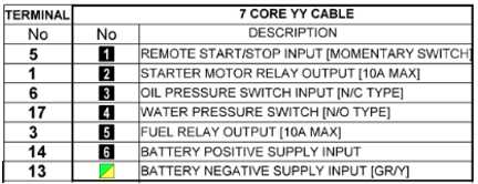
The module is directly wired with to the pump according to the above table and the module itself is situated next to the Autonomous and Relay Modules on a set of shelves on the right wall of the shed.
Pump control module setup
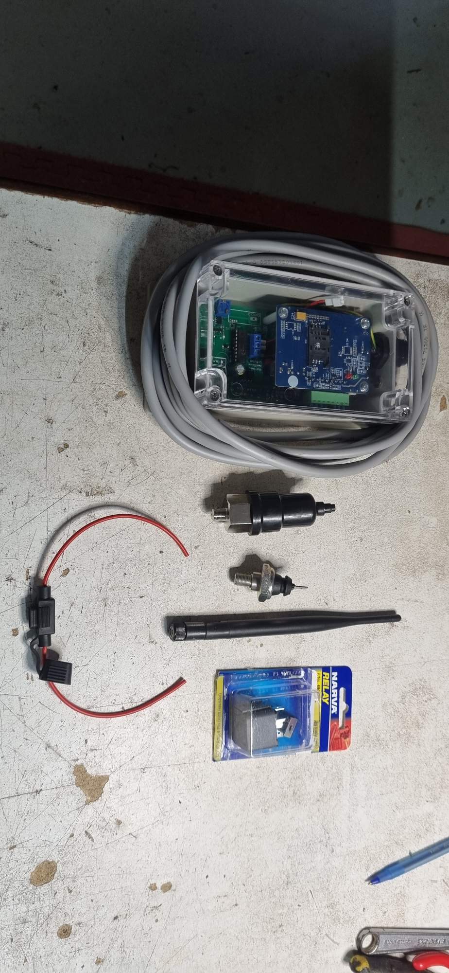
The pump’s direct key start is supplemented by a SFS01-V2-3G diesel pump control module. These are sold by Small Farm Services as a DIY kit for $1995. A further RF capability in the module (minus his RF wall switch) costs an additional $335. SFS will pre-wire up this module to the pump for an additional cost of $1,390. In this installation the pump was DIY wired to the supplied control box kit (including the RF capability). This requires wiring the following: 1 x oil pressure switch 1 x water pressure switch [needs to be drilled and tapped into water pump outlet] 1 x inline fuse 1 x 4G stub antenna 1 x slave relay for starter motor solenoid
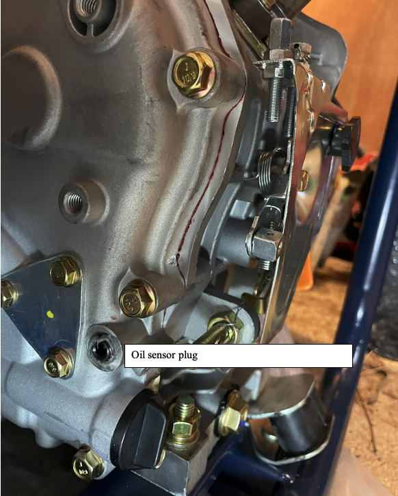
An Oil Pressure Sensor is provided and needs to be screwed into the pressurised oil gallery on the back end (pump end) of the engine. For the 188FV diesel engine a port is provided for this (31 in the expanded cylinder block diagram) and is accessed by removing the plug with an Allen key.
The port is as shown:
Installation required drilling and tapping a hole in the cast iron outlet of the pump with thread 1/8” NPT to accommodate the water sensor. For drill size 0.332 inch = 8.433 mm:

A variable speed hand electric drill was used to drill into the side of the outlet, initially with a smaller diameter 3mm cobalt drill then stepping up to the correct diameter 0.33 inch = 8.4 mm. The tap was lubed with cutting compound when tapping the thread.
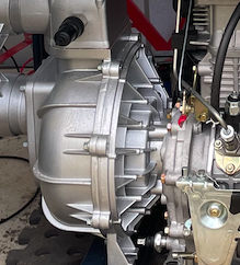
Pump with oil and water pressure sensors installed
Basic harness is a 7 core YY cable which is laid up in black with white consecutive numbering.
The wiring to the control unit bus cable is as follows:
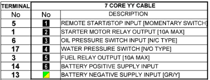
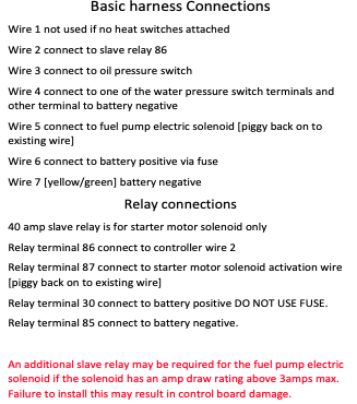
Wiring to the pump is as below:
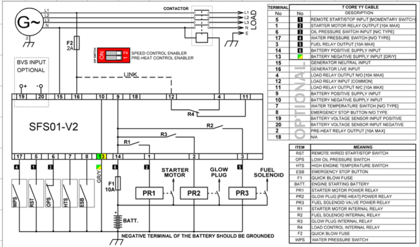
Note that Remote Start Switch RST toggles start and stop each time it opens or closes. When start is triggered it activates the starter motor through PR1 and (R1). When stop is triggered it turns off the fuel solenoid through PR3 (and R2).
{ The wired remote control of the SFS01-V2 is available through terminals 5 and 13 (using momentary N/C switch). } Terminal 13 is -ve earth. Terminal 5 (Wire number 1) is the wired remote stop/start control wire. [The manual provided contains a systematic error based on a previous now surplanted model where the pump was activated by closing a N/O circuit. As Graeme Lund confirmed the new model is the reverse configuration and is as set out below.]
{ The pump is activated when the N/C switch is opened. } Thus one or more N/C switches placed in series in wire 1 when opened will set the pump running. The pump can later be turned off using the remote capabilities.
{ For the Arduino the Songle 5V relay with pin IN pin can be connected to the corresponding Arduino GPIO2 pin. } Then for the relay connections numbered 1, 2, 3 from left as below, the pump remote start switch circuit should be connected across 2-3 which is normally closed (ie closed when IN is HIGH – since Songle relays activate on LOW).
Connectors
The pump control module requires the following
- Wired remote start – two pin with one pin connected to battery -ve and the other via wire 1 to terminal 5 of the controller. Any sensor intended to trigger the pump on thus must open the wire 1 circuit.
- Charger – two pin connected to corresponding terminals of the battery.
- Controller – 6 pins with each pin corresponding to the numbered wires 2-6 on the controller bus.
Spade and bucket connectors were used to enable easy disconnection and reconnection for test and other purposes.
Manual remote control features
When operating in remote mode under Home Assistant control rather than autonomous mode, the system provides operators with control options that balance automation convenience with manual oversight. The manual intermittent sprinkler system for P1 exemplifies this balance.
Master lock control: A LOCK control system set in the ARMAC Home Assistant dashboard provides a master safety mechanism to avoid inadvertently triggering valves, and particularly the pump, for example through a 'pocket dial'. When LOCK is active, the dashboard cannot turn on P0 (pump), P1 (sprinkler), P3 (high flow) or P4 (gel). Shed cooling (P2) is treated differently: under LOCK the Disable Shed Cooling switch can be turned on (stopping cooling) but not off - the lock can always stop water use, but never start it. LOCK guards against remote operation only: Autonomous mode is not stopped by LOCK, and may run the pump, spray and inject gel while the lock is on.
The LOCK signal propagates through the entire system architecture. AR1 includes LOCK state in every command frame it sends (CMD:...LOCK:0/1...) and in every status frame (STAT:...LOCK:0/1...). AR3 extracts LOCK state from these frames and stores it in a local variable. Before executing any pump command, AR3 checks LOCK status and forces the pump request to off if LOCK is active. Before setting peripheral outputs P1, P3, or P4, AR3 checks LOCK and forces them off if LOCK is active.
A particular safety scenario arises when LOCK engages while the pump happens to be running. This might occur if an operator activates LOCK while running the pump from the dashboard. To handle this case in remote mode, AR3 implements active LOCK enforcement: if LOCK is active AND the pump is currently on, AR3 requests pump-off every 500 milliseconds until the pump state changes to off. This does not apply in Autonomous mode, where it would fight the autonomous logic. This "kicking" behavior ensures that LOCK enforcement cannot be circumvented by timing issues where the LOCK signal arrives between command evaluations, and ensures that the pump turns off within about half a second of LOCK activation. AR1 always starts up locked, and the dashboard shows the effective lock, which is also on whenever Autonomous mode is active.
The LOCK system is a defence-in-depth safety approach—both AR1 and AR3 enforce LOCK, so even if RS-485 communication partially fails such that AR3 doesn't receive updated LOCK status, AR1 will refuse to send pump-on commands, and even if AR1's enforcement fails, AR3 will refuse to execute them.
The user can configure intermittent sprinkler timing via two dashboard dials labeled TimeON and TimeOFF, each accepting values from 0 to 30 minutes, set with - and + buttons (one minute per tap; the value is sent two seconds after the last tap, and the settings are kept when Home Assistant restarts). These values are transmitted from Home Assistant to AR1 via MQTT topics home/peripheral1/TimeON and home/peripheral1/TimeOFF. AR1 stores them both in RAM variables for immediate use and in EEPROM for persistence across power cycles, ensuring that manually configured timing survives Arduino reboots without requiring re-entry. AR1 then forwards these values to AR3 via RS-485 configuration frames in the format CFG:INT|ON_MIN:n|OFF_MIN:m, allowing AR3 to potentially use them, though in practice AR3's autonomous mode ignores these settings and uses its own built-in timing tables.
AR1 implements the intermittent cycling locally for remote/manual mode operation, providing two distinct driver modes that the operator can select. In recirculation mode, when the operator enables peripheral1 (sprinkler system), AR1 first ensures the pump is running, then begins cycling P1 according to the configured timing. Each cycle consists of TimeON minutes with water going to the sprinklers (valve relay off, pass-through) followed by TimeOFF minutes with the water recirculated to the tank (valve relay energised). The pump remains continuously on throughout this cycling.
In pump mode, AR1 takes a different approach: when the user enables peripheral1, AR1 sets P1 to pass-through and leaves it there continuously. Instead of cycling the valve, AR1 cycles the pump itself, turning it on for TimeON minutes and off for TimeOFF minutes. This mode reduces total pump runtime and can be more efficient for very long off times because the diesel engine cools between cycles and the battery has opportunity to recover some charge.
However, pump mode carries risks that recirculation mode avoids. Each pump start consumes significant battery power through the diesel starter motor, potentially 200 amperes for several seconds. If battery capacity is marginal, the pump might fail to restart after an off cycle. Additionally, frequent pump starting causes wear on the diesel starter motor and the engine itself, potentially shortening service life. For these reasons, AR1 implements safety gates that must be satisfied before pump mode is allowed.
Before permitting pump mode operation, AR1 checks that battery voltage, from its own reading, exceeds 12.25 volts; with no valid reading, pump mode is not allowed. Below this threshold, the battery is considered insufficiently charged to reliably restart the pump, and pump mode is forbidden.
AR1 also requires that both TimeON and TimeOFF exceed 10 minutes. This minimum cycle time prevents excessive starter wear that would result from very rapid cycling—if cycles are shorter than 10 minutes in either phase, recirculation mode must be used instead.
If the user has requested pump mode via the Home Assistant dashboard but these safety conditions are not met, AR1 automatically downgrades to recirculation mode and publishes a status message to MQTT topic home/sprinkler/driver/info with the content "DOWNGRADED". The dashboard can display this message, informing the operator why their selection was overridden.
When conditions improve (battery charges above threshold, or operator increases timing values above 10 minutes), AR1 upgrades to pump mode and publishes status "PUMP".
This automatic mode selection ensures that the system never enters an unsafe configuration while still giving the operator maximum control authority when conditions permit.
A special case exists when both TimeON and TimeOFF are set to zero. Intuitively that suggests "don't cycle the water on and off", so consistent with that AR1 sets the valve to allow water through uninterrupted irrespective of pump/recirculation mode. That is, the P1 valve is set to pass-through position and remains there.
The shed cooling system (P2) offers analogous flexibility via TimeON2 and TimeOFF2 configuration.
For shed cooling, when both TimeON2 and TimeOFF2 are set to zero, P2 follows the pump: it comes on when the main pump starts and turns off when the pump stops. This pump-linked mode provides passive shed cooling whenever the diesel pump is running without requiring the operator to manage shed cooling separately.
When TimeON2 is greater than zero and TimeOFF2 is zero, P2 operates in forced continuous mode regardless of temperature. This allows the user to force cooling on continuously if they want maximum cooling. When TimeON2 is zero and TimeOFF2 is greater than zero, P2 is kept off and no cooling water flows. When both values are greater than zero, P2 runs timed intermittent cycles identical to P1's recirculation mode behaviour.
Development mode. The AR1 Development Mode switch on the System Health dashboard makes AR1 clear the relay and timer settings to safe defaults on every restart, for safe testing during code development. Normally it is off, and the settings are restored after a restart.
Last checked against the code: 7 November 2026. The relays and their default positions are listed in Modules and relays.
<< Autonomous Fire Defence Algorithms | | Home Assistant and the Raspberry Pi >> |Table of Contents>