
The water storage and delivery system forms the backbone of ARMAC's capability. Water pressure can drop to close to zero in the time of a bushfire and a self-sufficient water supply is crucial.
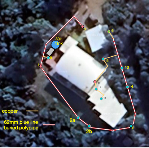 |  |  |  |  |
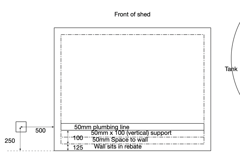
| Feeder pipe and sprinklers | Tank layout design | Tank, shed and vacuum breaker | Pump system | Feeder pipe under construction |
(click photos to enlarge them)
The tank
As in the location of this system, there are practical limits on how much water can be stored. For this system, a 30,300-litre Aquaplate tank (3.5 metres diameter, 3.1 metres height) in shale grey Colorbond provides the primary water reserve. The tank sits on a compressed crushed rock base positioned next to a side deck of the house. Its outlet to the pump is DN50 (2" internal diameter).
A replenishment pipe from the house mains runs to the top of the tank, and thence to a 3/4" stainless steel floating ball valve, which automatically refills the tank after use. The valve is rated to 1.0 MPa, which exceeds normal residential water pressure (0.3-0.5 MPa). Mains top-up through the float valve refills at about 15 L/min - far less than the pump draws, so it is the tank, not the mains, that carries the defence.
Measured performance (house water-meter test): the tank fills to 2.94 m of water - about 95 litres per centimetre of depth, or about 27,900 litres, of which about 27,500 litres is usable down to the 0.05 m dry cut-off. The system delivers 147 L/min in reduced-flow mode, giving about 187 minutes (just over 3 hours) of continuous spraying from a full tank, extending to 10 hours or more when operated in intermittent cycles with appropriate on/off timing. In high-flow mode it delivers 217 L/min, also checked against the water meter, giving about 127 minutes (just over 2 hours) of continuous spraying from a full tank.
The depth of water is measured by a pressure sensor lying on the bottom of the tank, its cable protected in a fire-resistant silicone sleeve fixed along the recirculation pipe (see Sensors).
The pump

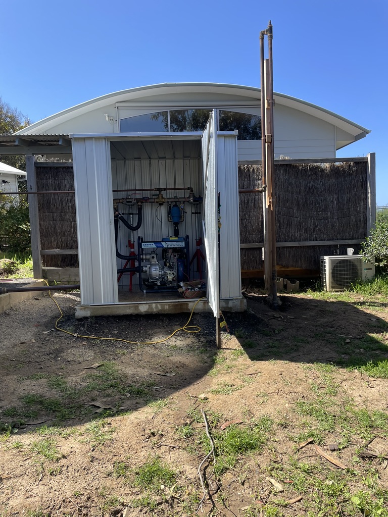
Water delivery to the sprinklers is accomplished by a Garpen WP3DELHPS diesel-powered pump: an 11 horsepower electric-start engine with a 3-inch single-impeller high-pressure pump, mounted on the shed's concrete floor (dimensions 500 long × 600 wide × 900 high mm). The manufacturer specifies maximum head of 70 metres (equivalent to 720 kPa pressure) and maximum flow of 630 L/min - easily enough for the 95-220 L/min required in this system.
Actual performance is less in practice than the specifications. Graham Lund, formerly at Small Farm Services, carried out a bench test of a 3" 10 hp Garpen pump with 2" inlets and outlets:
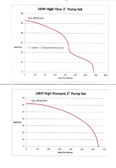
From this the WP3DELHPS, with a 3" to 2" reducer on the outlets, should realistically produce about 50 metres head at 130 L/min and 45 metres head at 300 L/min (perhaps up to 10% more at maximum revs, since this is an 11 hp pump). The pump comes with 3" outlets and hose tails; on the basis of these curves the inlet and outlet were reduced to 2" using brass and stainless steel reducers.

The pump's 13-litre diesel tank on its own provides approximately 6.5 hours of runtime at the 2 L/hour consumption rate. To extend this, a 24-litre reserve tank (fitted with an electronic fuel-level sender) is mounted on a galvanised steel frame in the pump shed, in parallel with the existing tank: its hose joins the 13-litre tank's hose through a T barb, with the two tanks' fill levels matched so they draw down together. Together the two tanks give approximately 17 hours of continuous running, and longer when the sprinklers are run intermittently. A solenoid in the fuel line allows the pump to be stopped remotely. Oil and water pressure switches show whether the engine is running and the pump delivering (see Sensors).
The electric start system is controlled by the SMS-based SFS01-V2 pump control module, which can also be commanded by the ARMAC control system through a relay - and, when set to do so, ARMAC can crank the engine itself (see Output Control and Safety Interlocks).
The feeder pipe
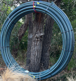
The buried feeder pipe network consists of 100 metres of DN50 (63 mm external diameter) high-pressure blue-line polypipe, chosen for its exceptional pressure rating and resistance to heat damage when buried at adequate depth.
Although greenline (rural) polypipe would probably have coped with the pressures involved, the desirability of robust piping for what will be an intermittently tested but critical system led to the much more robust (metric) blue-line pipe and fittings. Pipe size was then settled by friction loss:
| Blue-line pipe | Friction at 200 L/min | Friction at 300 L/min |
|---|---|---|
| 63 mm external (50 mm internal) | 4.55 m head per 100 m | 8.63 m head per 100 m |
| 50 mm external (40 mm internal) | 13.73 m head per 100 m | 26.12 m head per 100 m |
Hence 63 mm blue-line pipe was selected. As the pump curves show, pressure at each sprinkler, even at the end of the pipe, remains adequate for all the sprinkler heads; the elevation of the sprinklers nowhere costs more than about 5 metres of head. It was nevertheless essential to regulate flow at each sprinkler head using a ball valve to balance the system (see Sprinklers and pipework).
The pipe was laid in trenches generally 250-350 mm deep, well exceeding the 100 mm minimum depth recommended by CSIRO research for protection against radiant heat from burning surface fuels. (As Justin Leonard puts it, a 100 mm minimum depth is adequate "unless a vehicle or pile of wood or a fence is burning above the line, in which case needs to be deeper" - see Bushfire Resilience: sprays.) At critical locations where trenches were shallower due to rock or tree roots, earth was backfilled above the pipe to ensure adequate coverage. Saddle clamp fittings at each sprinkler location allow copper risers to tap into the feeder pipe without compromising its pressure integrity.
Anti-siphon control
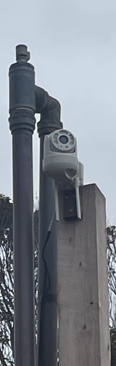
Since multiple sprinklers sit below the water level in the elevated tank, an anti-siphon system prevents water from draining through the pump and sprinkler network when the pump stops. The solution employs a vacuum breaker: a brass tee fitting with an air intake check valve, combined with an elbow, mounted on a dedicated post at the high point in the system. When pump pressure ceases, air enters the system, preventing siphon action that would otherwise drain the tank through the lowest sprinklers; while the pump runs, the check valve holds the water under pressure. The video camera is mounted on the same post.
 |  |
Figures on this page are also listed in Key data. How the water system was planned and how it changed along the way: Development history: the water system. Last checked: 7 November 2026.
<< Remote recovery run sheet (Raspberry Pi) | | Sprinklers and pipework >> |Table of Contents>