
Architecture
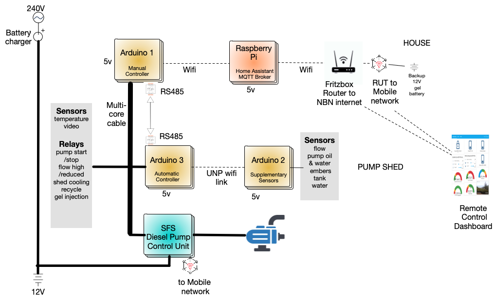
ARMAC Electronic System Overview (click to enlarge)
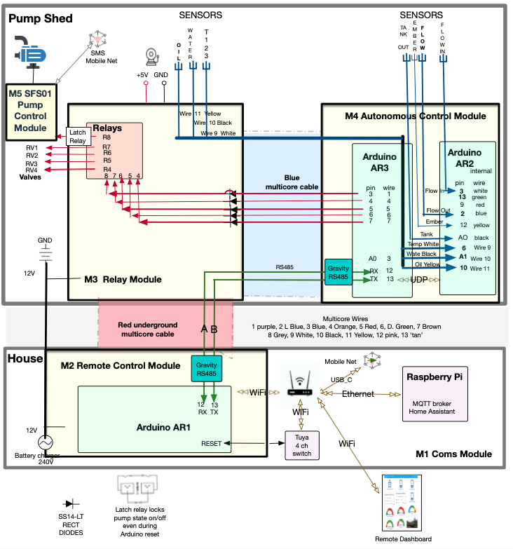
ARMAC Electronic Control System Detail (click to enlarge)
In designing this system it became clear that bushfire defence for residential properties presents some complex interacting challenges. The system must operate reliably under extreme environmental conditions, make sensible decisions in the absence of human oversight, conserve finite water resources while providing adequate protection, and keep working even when the main communication networks fail. ARMAC addresses these challenges through a five-module design with distributed computing, redundant communication paths, a broad set of sensors, and autonomous decision-making - principles usually associated with industrial control systems and life-safety applications, adapted to the needs of residential bushfire defence.
Three design principles inform every part of the implementation. First, resilient operation through redundancy keeps the system working even when individual components or communication links fail. Second, autonomy lets the system make appropriate defensive decisions from real-time sensor data, without human intervention at critical moments. Third, distributed computing avoids single points of failure by giving specific responsibilities to specialised modules that can work semi-independently while coordinating over several communication channels.
The physical implementation consists of five distinct modules, each housed in its own enclosure. The two house modules are responsible for communication with the outside world; the relays, the sensors and the autonomous decision-making are in the pump shed. The module contents are listed in Modules and relays, and every pin in Arduino pin allocations.
Module 1: Coms Module,
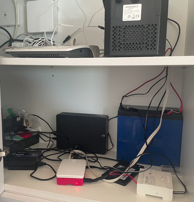
Mod 1 (click to enlarge)
Module 1 is located in the house in direct connection with the NBN cable, is the network and control hub. It contains a Fritzbox router providing the main NBN connection, a Teltonika RUT240 mobile router for failover internet access, and a Raspberry Pi 4B (4 GB), all supported by battery backup. The Raspberry Pi runs Tailscale (with ZeroTier One as a fallback, and a reverse SSH tunnel to the project VPS) for secure remote access, Home Assistant for the web-based control dashboard, and Mosquitto as the MQTT message broker (see Home Assistant and the Raspberry Pi). A Tuya network-controllable relay board allows the Raspberry Pi (switch 1) and the Fritzbox (switch 2) to be power-cycled remotely if required. It is joined to the RUT240's own WiFi rather than the Fritzbox's, so that it stays reachable when the Fritzbox has failed; since the RUT240's mobile data is normally left off and turned on by SMS when needed, the board shows as offline in the Tuya app at other times - and turning on the RUT240's mobile data by SMS (mobileon) is a necessary first step before either switch can be used (see Troubleshooting). With these components this module provides the main human interface to the system, and keeps the connection going through power outages and failures of the main network.
Module 2: Remote Control Module
Mod 2 (click to enlarge)
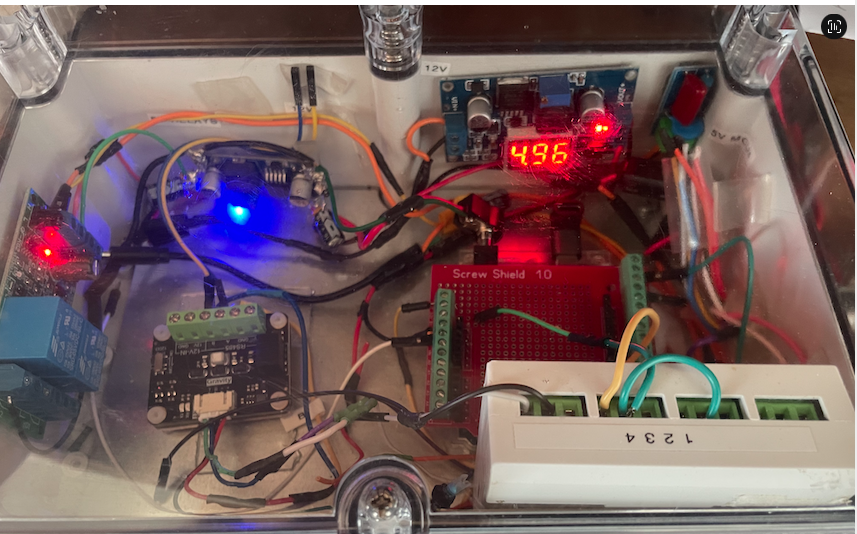
Module 2 is also in the house and contains Arduino AR1, an UNO R4 WiFi microcontroller that is the critical bridge between the home network and the pump shed. It communicates with Home Assistant over MQTT, while managing the RS-485 link (and its backup serial link) to the shed over the underground multicore cable. It is powered from the shed battery, and reads that battery's voltage. Placing this module in the house rather than the shed keeps the main control interface in good contact with the house WiFi and the mobile network, and means the long link to the shed is handled by robust wired RS-485 rather than less reliable wireless.
Module 3: Relay Module
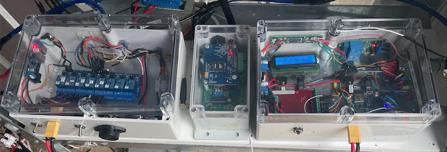
Mod 3 (click to enlarge)
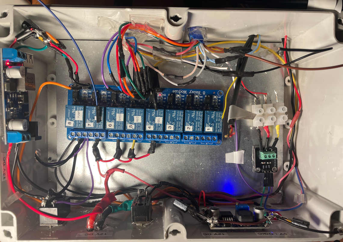
Module 3 is the relay control hardware, in the pump shed. It contains the strip of Songle 5 V relays that operate the sprinkler system valves, powered through a 12 V to 5 V step-down module from the shed battery, with the relays' logic inputs connected to the corresponding pins of Arduino AR3 by the blue multicore cable. It also holds relay R8, which passes the pump-control signal on to the SFS01 pump controller, a manual isolation switch that allows the pump to be isolated during maintenance (with a buzzer that can stand in for the pump during testing), and the optocoupler board for the oil and water pressure switches. The temperature sensors, though spread around the property, have their connection points in this module, their signals combined onto a single wire before going on to Module 4. Concentrating the relay hardware in one module simplifies wiring, eases troubleshooting, and gives a clear physical separation between the control logic and the high-current switching. The relays and their default positions are listed in Modules and relays.
Module 4: Autonomous Control Module
Mod 4 (click to enlarge)
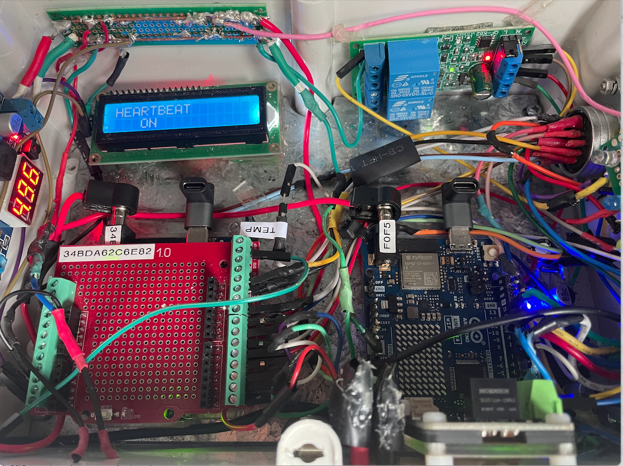
Module 4 is the control and sensor hub. It contains two Arduino UNO R4 WiFi microcontrollers working together, the pump latch relay, the LCD display and the test button. Arduino AR2 runs its own WiFi access point and is the sensor hub, reading all the physical sensors and broadcasting the readings by UDP. Arduino AR3 joins AR2's WiFi network, receives those readings, runs the autonomous fire defence algorithms, drives the relays, and handles the RS-485 link back to the house. Separating sensor reading from control logic lets each Arduino concentrate on its own task, stops sensor-reading delays from interfering with communications, and keeps the sensor data flowing even if the control logic has problems. The tasks involve some complex timing, which becomes much easier with the two Arduinos given quite different roles.
The pump latch relay beside AR3 is a low-current signal relay whose job is to hold the pump-state signal steady through an AR3 reset. AR3 pulses its inputs; its held output travels on blue multicore core 1 to relay R8 in Module 3, which passes the signal through the manual isolation switch to SFS01 wire 1. The SFS01 box then drives the high-current automotive starter relay (through its wire 2) that energises the starter solenoid. How the pump is controlled is described in Output Control and Safety Interlocks.
Module 5: Pump Control Module
Mod 5 (click to enlarge)
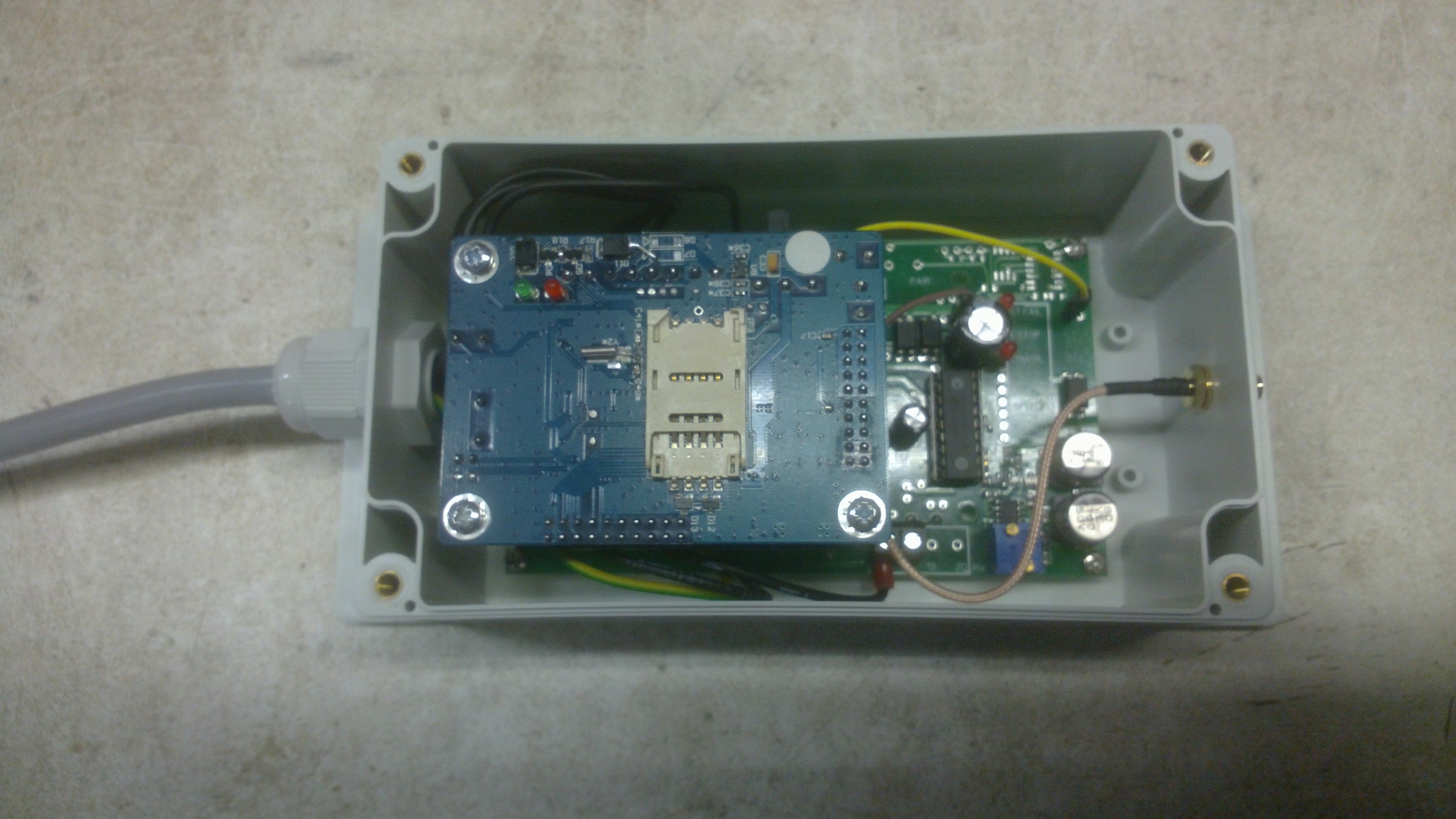
Module 5 is the Small Farm Systems SFS01 commercial pump controller, a dedicated unit responsible only for the diesel pump. It takes commands both from ARMAC, through relay R8 and wire 1, and by SMS over the mobile network. These two paths mean the pump can still be commanded if the local control system fails completely, while the commercial controller provides tested pump management, including its own safety interlocks. If the pump does not start on a START command, it retries after 20 seconds, up to 5 times. When set to BYPASS mode, ARMAC can instead crank the engine itself (see Output Control and Safety Interlocks). Its mobile antenna sees out through a 300 × 300 mm magnesium oxide panel set into the shed wall beside it.
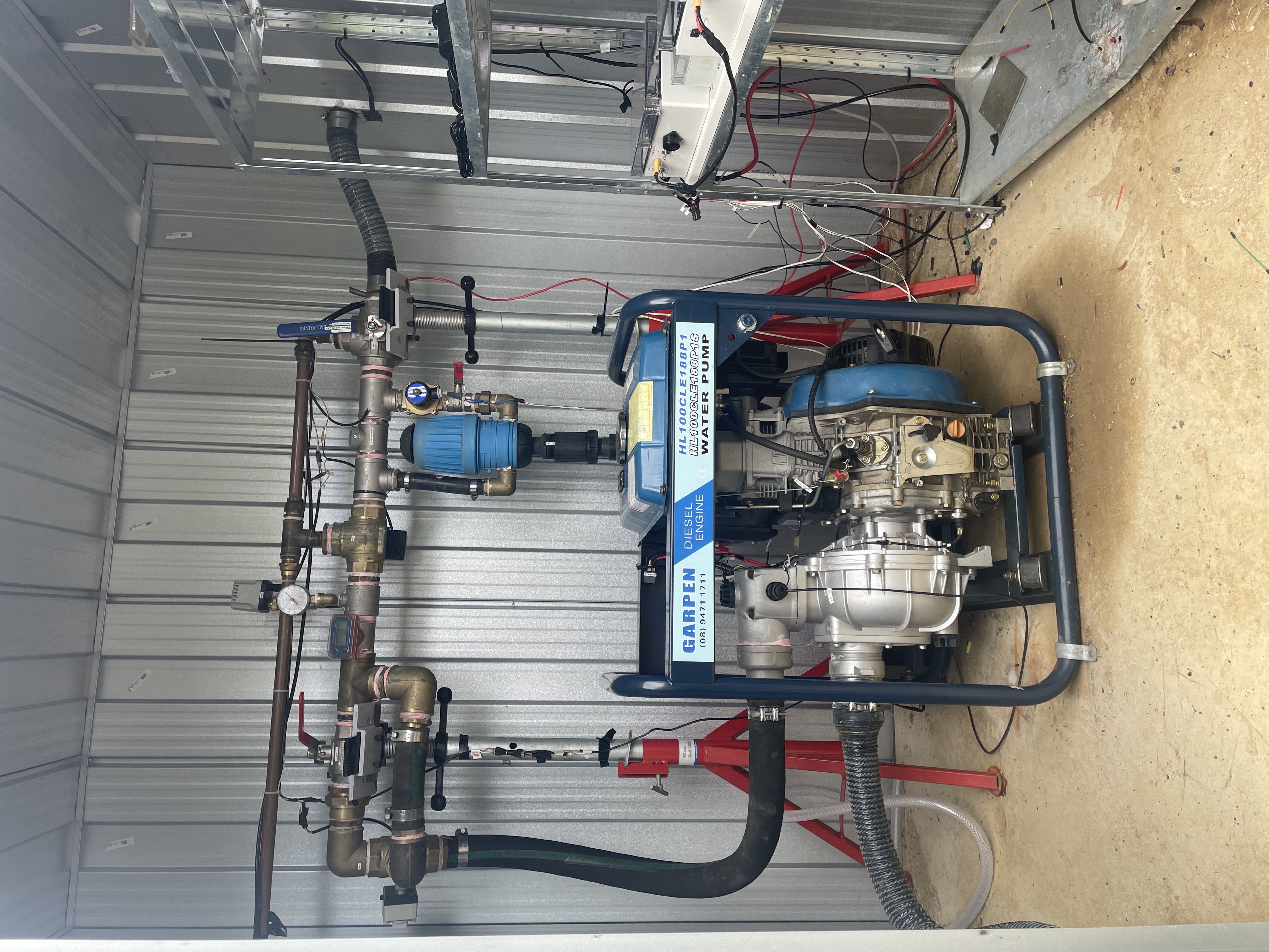
Links between the house and the shed
Two cables run underground to the pump shed. The first is a 13-core irrigation solenoid control cable, of which only four cores are needed: two for the RS-485 link and two for the backup serial link (see Communication protocols and Multicore cables). The second is the heavy 12 V power cable linking the shed battery to the charger in the house (see Battery, charging and power distribution). Care is taken that all systems share a common earth at the battery's negative terminal.
Watchdog protection
Two kinds of watchdog keep ARMAC working if one of its microcomputers freezes or a communication link drops: a hardware watchdog inside each Arduino, and software watchdogs that check the links between the modules.
Hardware watchdog (inside each Arduino). Each Arduino UNO R4 WiFi has a watchdog timer built into its processor. The program must reset this timer at least every few seconds. If it fails to - because the program has frozen, for example waiting on a WiFi or display command that never returns - the processor restarts itself and the program starts again from the beginning. The longest interval the chip allows is about 5.6 seconds, so the sketches set 5 seconds.
- For the watchdog to help rather than harm, no deliberate wait in a program may be longer than that interval. Waits are therefore bounded: each command to the Arduino's WiFi chip is limited to 1 second, joining a WiFi network to 3 seconds, and an MQTT connection attempt to about 4.5 seconds; inside longer waits (such as waiting for WiFi to connect) the timer is reset as the wait proceeds.
- AR3 checks at start-up that its LCD display is actually present before using it, since writing to a missing display would stall AR3 long enough to trigger the watchdog over and over (a restart loop).
- After a restart, AR1 reconnects to WiFi and Home Assistant within about 20-30 seconds, and each Arduino comes back in the mode it was in (see Restart safety below).
- Tested on TestSys: AR1, deliberately frozen, restarted itself after 6 seconds and was back on Home Assistant 21 seconds later; ten minutes of failed connections to an unavailable MQTT broker caused no false restarts.
Software watchdogs (links between modules).
- Heartbeat, AR1 to AR3. AR1 sends a heartbeat to AR3 over RS-485 every 5 seconds. If none arrives for 1 minute AR3 shows a warning; after 5 minutes without a heartbeat AR3 takes control in Autonomous mode. Control is handed back once the heartbeat has been steady for 15 seconds - in practice about 15-20 seconds after Autonomous Mode is switched off in Home Assistant (see The Heartbeat System and Mode Transitions).
- Home Assistant link, AR1. If AR1 loses its MQTT connection to Home Assistant for 5 minutes it stops the heartbeat, so that AR3 takes over as above. Meanwhile AR1 keeps retrying - WiFi every 30 seconds, MQTT every 15 seconds - and after 15 minutes restarts itself. When MQTT returns, AR1 goes back to remote control, provided the system was in remote control when the link was lost; if it was already in Autonomous mode it stays there.
- RS-485 link, AR1 and AR3. If no sensor report reaches AR1 over RS-485 for 15 seconds, AR1 switches to the backup serial link and Home Assistant raises a communications alert; it switches back once RS-485 has been steady for 60 seconds (see Communication protocols).
- Sensor link, AR2 to AR3. AR3 reports the AR2 WiFi link as lost if no sensor data arrives for 25 seconds, and treats flow readings older than 3 seconds as zero.
Restart safety and connection self-restarts
With working watchdogs on all three Arduinos, no physical remote reboot switch is needed.
- A restart keeps Autonomous mode. Each Arduino remembers its mode in its own memory (EEPROM), which survives a restart or power cut. AR1 comes back in the mode it was in, and AR3, if it was in Autonomous mode, resumes it at once - at the same fallback stage and with the same tank estimate, saved while it runs (see Autonomous Fire Defence Algorithms). After a restart AR3 also tells AR2 to stop any test simulation that the restart cut short.
- Connection self-restarts. An Arduino whose program keeps running but whose connection has failed is not caught by the hardware watchdog, so each one also restarts itself after a long loss of connection. A restart also resets the Arduino's WiFi chip, the usual culprit.
- AR1: no MQTT connection to Home Assistant for 15 minutes.
- AR3: no sensor data from AR2 for 15 minutes - but never while the pump is running or Autonomous mode is spraying, cooling or in a fallback stage.
- AR2: no message from AR3 for 25 minutes (longer than AR3's 15, so AR3 restarts first). AR3 sends AR2 a short message every minute while it is receiving AR2's readings, so silence means AR3 is no longer hearing AR2. A device merely connected to AR2's WiFi access point does not count.
- Safeguards against a restart loop: none of them restarts for this reason within 30 minutes of starting up, and each allows at most 4 such restarts in a row. AR1 then stops trying until the connection comes back, which resets the count; AR2 and AR3 instead slow down to one attempt an hour, so that a fault that clears later is still recovered.
- Home Assistant switch. Connection self-restarts on the System Health dashboard turns these restarts off (or on) on all three Arduinos: AR1 passes it to AR3, and AR3 to AR2, within a second or so. Each keeps the setting through restarts. It does not affect the hardware watchdog.
- Why each Arduino last restarted is shown in the Restarts card on the System Health dashboard: Power on, Watchdog, Software / upload (a new program loaded), Reset button, Connection check, or HA command (AR1 restarted through the hidden "AR1 Reboot" maintenance control - see Home Assistant and the Raspberry Pi).
- Testing. On TestSys the AR1 and AR3 limits are 3 minutes (and 2 minutes after start-up) so they can be tested quickly; AR2 uses the full times. All of these have been tested on TestSys, including restarting AR1 and AR3 during Autonomous mode and AR3 in the middle of a fallback stage (see Test scenarios).
Communications resilience
The system reports over WiFi and switches up to eight relays. Given that the mobile network and the NBN are both vulnerable in a fire, the aim is maximum control redundancy, so both the NBN and the 4G mobile network are used to provide internet access wherever possible. The Teltonika RUT240 router, running at 9-30 V DC with a 4G SIM card, provides the fallback to the mobile network when the NBN is unavailable. Its mobile data is deliberately left off, to save the SIM's data, and is turned on (and off) by SMS (mobileon / mobileoff). The RUT240 is connected to the Fritzbox by USB, and the Fritzbox's failover protection is enabled: if the NBN connection has failed for 10 minutes, the Fritzbox switches to the RUT240's mobile connection, and it returns to the NBN once that has been working again for 20 minutes. The whole house network - the Raspberry Pi, Home Assistant and AR1 included - then reaches the internet through the mobile network, without any change on the devices. The intention is that when a bushfire threat is imminent the mobile data is turned on, so that this failover can take place if the NBN connection fails. Turning it on is also the necessary first step before the Tuya relay board can be used to power-cycle the Raspberry Pi or the Fritzbox. (Experience so far is that when the Fritzbox itself hangs, failover does not rescue the connection: power-cycling the Fritzbox does.) It can also use another device's WiFi as its internet connection, act as a gateway or node in a mesh network, and serve as a WiFi access point for other devices. (One was bought on eBay for $180.)
Possible improvements to automatic recovery. The Raspberry Pi already restarts itself if it hangs (see Home Assistant and the Raspberry Pi). Three further options are under consideration, best tried first on the Rowe Street Pi:
- Automatic Fritzbox recovery. If there has been no internet for about 30 minutes, the Pi first asks the Fritzbox to restart itself through its local control interface (TR-064); if there is still no internet 10-15 minutes later, it power-cycles the Fritzbox with Tuya switch 2, controlled locally over its own WiFi link to the RUT240 (so neither the internet nor the Tuya cloud is needed), with the off period set as a countdown in the Tuya board itself so that power always returns. Attempts would be limited (say once every 2 hours, at most 3 a day), and a message sent when the internet returns. This needs a Fritzbox user for the restart command and the Tuya board's local key. The Tuya app remains the manual backup.
- A backup route for the Pi. When the NBN fails, the Fritzbox's own failover reconnects the Pi through the RUT240. But if the Fritzbox itself hangs, the Pi - which reaches the internet only through the Fritzbox, although it is also connected to the RUT240's WiFi - is cut off, along with its remote access paths (Tailscale, ZeroTier, the SSH tunnel), even with the mobile data on. A backup route through the RUT240's WiFi, used only when the Fritzbox route fails, would bring them back through the mobile network in that case.
- The Pi turning on the RUT240's mobile data. As the first step of automatic recovery, the Pi could turn on the RUT240's mobile data itself over the same WiFi link, power-cycle the Fritzbox if needed, and turn the mobile data off again afterwards - removing the need for anyone to send an SMS. This needs the RUT240's administrator login stored on the Pi.
A possible later addition is a Swarm M138 satellite transceiver modem ($299, robotgear.com.au), with a data plan of about US$5 a month for 750 data packets of 192 bytes (144 kb a month). That would do for SMS-style commands but nothing more; Swarm covers Australia, and it would be impervious to the vicissitudes of the mobile and NBN networks during a fire. Whether it can carry SMS needs further investigation.
Protection
Operating in bushfire conditions imposes extreme stresses: temperatures that may exceed 100 °C, radiant heat in the kilowatts per square metre, voltage spikes from pump motor switching, and electromagnetic interference from the diesel's ignition system. Several layers of protection address these.
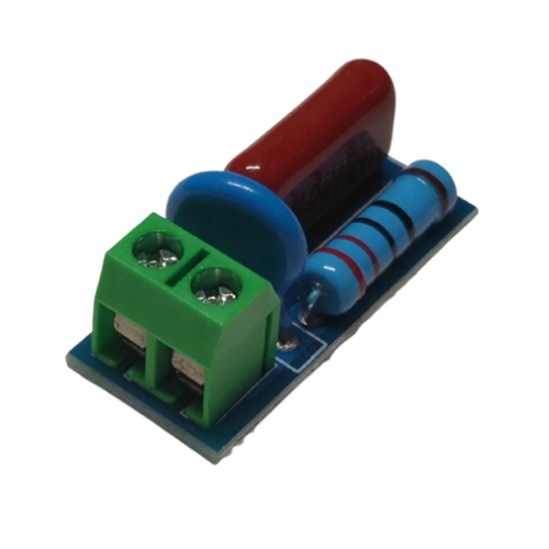
Snubber board filters voltage spikes
- Thermal protection. Temperature-sensitive components (electronics, plastic valve actuators) are protected by the shed cooling system (see The Water Control System: valves, flow modes and the pump shed).
- Separate supplies. Separate 12 V to 5 V buck step-down supplies, protected by snubber spike suppression, serve the logic and relay sides of the control system (see Battery, charging and power distribution).
- Electrical transients. Voltage spikes during pump starting (potentially exceeding 30 V on a 12 V system from inductive kickback from the starter solenoid) are suppressed by P6KE15A or 1.5KE18A transient voltage suppression (TVS) diodes across the battery terminals and at strategic points throughout the power distribution. These measures are summarised in Appendix 13.
- Signal lines. Each pin connected to off-board sensors or relays has 220-470 ohm series resistance followed by a P6KE6.8A TVS diode to ground and a 0.1 µF ceramic capacitor to ground: a three-stage network that limits voltage excursions, absorbs transient energy, and shunts high-frequency noise. Each connection between an AR3 pin and a relay input is also protected by a 1N5819 Schottky diode in series (with an acceptable 0.2-0.4 V drop).
- Interference. The RS-485 link between house and shed uses a 120 ohm termination resistor and ferrite core clamps where the cable enters the enclosures; its differential signalling gives excellent rejection of common-mode noise. Power supply lines have ferrite beads in series, which present a high impedance to high-frequency noise while letting DC pass.
- Communications. Several layers of command - from the internet over NBN or 4G, to the autonomous control in the pump shed itself, to SMS control of the pump through the pump control module - give layers of defence against communication failure.
- Water ingress. The two Arduinos, the buck converter power supply, the LCD and the RS-485 module are mounted in a sealed IP66-rated polycarbonate enclosure from Industrial Enclosures ($22 plus $11 shipping), rated for operation from -20 to 110 °C and flammable only at 960 °C. They depend mainly on spray cooling of the shed rather than insulation for thermal protection. The enclosure is mounted away from the shed cooling spray pattern, with two small baffled ventilation holes, one near the top and one near the bottom on the side away from the pipes, and the electronics on an internal metal plate to spread the heat. All external cable entries use cable glands with compression seals. The RS-485 transceivers, battery terminals and high-current relay contacts outside the sealed enclosure are positioned away from direct spray.
The heat generated inside the enclosure is small:
| Source | Heat |
|---|---|
| Two Arduino R4 WiFi boards | 1-2 W continuous (0.3-0.8 W each under WiFi load) |
| Buck converter | about 0.1-0.3 W |
| LEDs (half on) | about 0.12 W |
| RS-485 transceiver | 0.1-0.3 W |
| Total | about 1.5-2.5 W |
Antennas
Since the metal shed is almost a Faraday cage, the mobile and WiFi signals either had to be let in through a non-metallic section of the shed wall, or the antennas moved outside, where they would be vulnerable to fire. A 300 × 300 mm magnesium oxide window was set into the shed wall beside the pump control unit, which was enough for it to reach the 4G mobile network. The main WiFi-dependent electronics were placed in the house, linked to the shed by the underground cable, while AR2 and AR3 talk to each other by WiFi inside the shed.
Last checked against the code: 7 November 2026. How the electronics evolved: Development history: the electronics.
<< Ember detector (planned) | | Communication protocols >> |Table of Contents>