
ARMAC has to keep working when the mains fails, as it usually does in a fire. Figures are also listed in Key data.
The shed battery
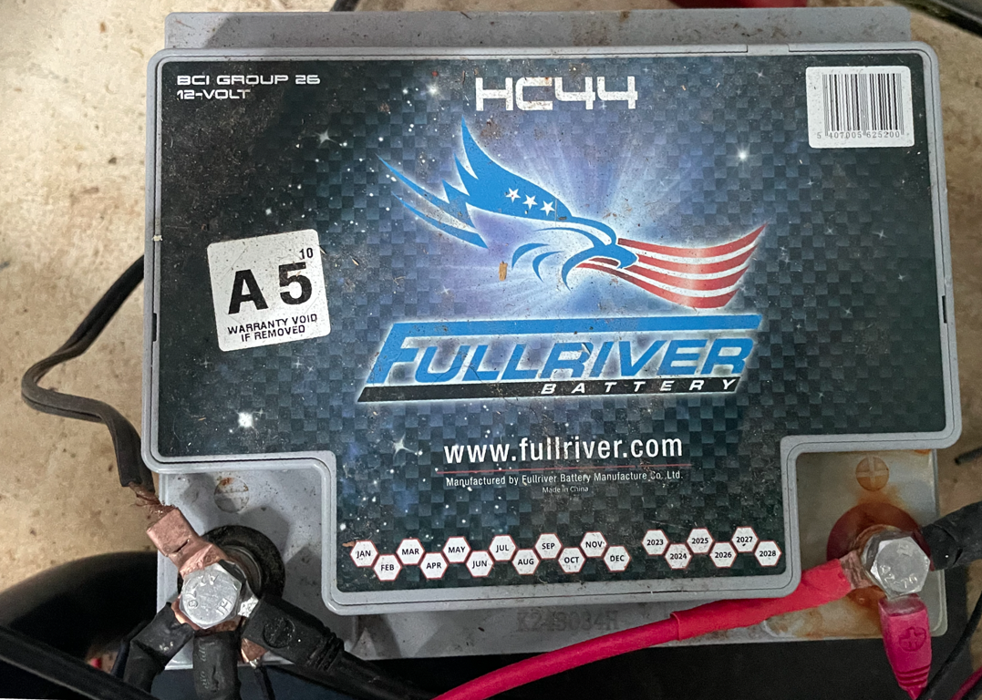
Fullriver HC44 12V 44AH Battery (click to enlarge)
The system's electrical power architecture centres on a Fullriver HC44 heavy-duty 12 V 44 Ah battery in the pump shed, providing 560 cold cranking amps - plenty for the Garpen pump's electric starter, which draws approximately 200-400 amperes for 2-4 seconds while cranking. The battery supports not only pump starting but also the motorised valve actuators (drawing approximately 0.8-1.2 A each during their 5-15 second movement), the relay coils, the pump latch relay, and all the electronic control systems in the shed. The 12 V 22 Ah gel battery originally supplied with the pump backs up Arduino AR1 in the house.
Charging. Battery charging uses a Victron Blue Smart IP65 10-ampere charger located in the house, connected to the shed battery by a robust two-core copper underground power cable. The charger implements multi-stage charging (bulk, absorption and float) with temperature compensation, preventing the overcharging that would shorten battery life while keeping the battery fully charged. In normal standby it holds the battery in float mode at approximately 13.5 V, ready for immediate high-current delivery. Charging history is available through its Bluetooth app (Victron Connect).
The cable. The positive cable needed enough capacity to avoid any significant voltage drop between the Bat+ terminal on the SFS01 pump control module and the battery, and to carry the charger's full 10 A. For a 12 V system with the voltage drop limited to 2-3% over 10 metres (20 metres there and back), that requires less than 0.0018 ohm per metre: 14 AWG or thicker would do, and 10 AWG was used. Care is taken that all systems share a common earth at the battery's negative terminal, which is also earthed with a stake.
How many starts? Experimentation shows that while the battery is charging, the pump can be stopped and restarted with no obvious effect on the battery. Based on 4-second cranking with an initial surge of 400 A and then 120 A in warm conditions, the theoretical capacity of the battery is in the order of 330 cranking attempts; with the engine currently needing two attempts to start, that comes down to some 165 starts. Conservative planning reduces this to 60-120 starts per charge, recognising that battery capacity falls with age, cold weather reduces it further, and voltage sag under heavy current may trigger low-voltage cut-offs before the battery is truly exhausted.
Battery voltage and the choice of cycle
Battery voltage, as read by AR1 (see Sensors), decides whether intermittent sprinkler cycles are made by stopping and restarting the pump, or by leaving the pump running and switching the recirculation valve between the sprinklers and the tank:
- In manual (dashboard) operation, pump cycling is allowed only above 12.25 V and when both the on and off times exceed 10 minutes; otherwise AR1 uses the recirculation valve.
- In Autonomous mode, at or below 12.0 V AR3 always uses the recirculation valve; above it, the pump is stopped and restarted only for cycles with more than 15 minutes off.
- With no battery reading (none received from AR1 for 5 minutes, for example when the link to the house is down), AR3 uses the recirculation valve, and AR1 does not allow pump cycling: there is more fuel than there are starts.
Pump cycling saves diesel at the cost of some battery power for each restart; valve switching saves the battery at the cost of continuous diesel use, which a full 13 L tank supports for about 6.5 hours. As discussed later, an additional 24 L tank has been added giving a total of about 37 L or 17-18 hours of continuous diesel use which might well be sufficient but can be further extended with the stop-start capability.
Power distribution
Power distribution from the battery uses two separate rails: a power rail for the pump starter, the valves and other high-current loads, and a logic rail for the Arduinos and sensors. LM2596 DC-DC buck converters step the 12 V battery voltage down to a regulated 5 V, with separate converters for the relay coils and for the Arduinos and sensors, so that noise from relay switching does not couple into sensitive analog measurements. Each converter output has a 470 µF electrolytic capacitor in parallel with a 0.1 µF ceramic capacitor, giving low impedance over a broad range of frequencies, plus ferrite beads on the output lines to suppress conducted interference. The tank level sensor loop runs from a regulated 12 V supply. Protection against voltage spikes is described in The Electronic Control Sub-System.
In the house
The communications module (Module 1: the routers and Raspberry Pi) runs from the mains with battery backup, so the internet link and the dashboard keep going through a power cut. Arduino AR1 (Module 2) is powered from the shed battery, and measures that battery's voltage (see Sensors).
Last checked: 7 November 2026. Earlier cable choices and thresholds: Development history: power.
<< Fire-Gel Dosing -- Needle-Valve & Dial Calibration | | Sensors >> |Table of Contents>