
ARMAC employs two distinct sprinkler types, selected after quite a bit of testing and hydraulic analysis, standing back from the house on posts and throwing their spray back over it. Why this approach was chosen over roofline sprays is explained in Key choices: wetting technology.
 |
The sprinkler heads
A large number of sprinkler heads are available. The requirements were all-metal, robust construction, easily removed and cleaned nozzles, part-circle adjustable spray, and spray radii appropriate to the pressures in the system. After considering these, two were selected:
- Three Dural VYRSA-60 dual-nozzle impact sprinklers (3.6 mm and 2.4 mm nozzles) serve areas requiring longer throw distances. They are designed to operate between 180 and 420 kPa, corresponding to a 13.0-14.5 metre radius and 15.3-24.0 L/min: 13 m at 180 kPa, and 14.1 m at 20.8 L/min at 320 kPa. Larger nozzles were available but were not used: they would increase flow, but shorten the time the water lasts. They are fed by 20 mm copper pipe.
- Ten Pope Heavy Duty Impact sprinklers handle closer-in coverage: a heavy-duty brass impact head, full or part circle, 1/2" thread, 10 L/min at the 100 kPa minimum pressure, 18.9 L/min at 350 kPa, 12.5 metre maximum radius, with stainless steel springs. (The same head is also sold for fire fighting, for example as the Rainmaker sprinkler with a gutter attachment.) They are fed by 15 mm copper pipe.
All sprinklers feature all-metal construction with easily removable brass nozzles for cleaning, and adjustable full or part-circle spray patterns. They are designed to be easily adjustable both horizontally and vertically.
The shed cooling sprays, not shown on the plans, are five 12 mm flat-fan sprays fed by 12 mm copper pipe and angled to cool the pump shed roof and walls (see The Water Control System: valves, flow modes and the pump shed).
Where they are
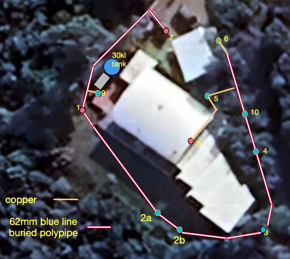
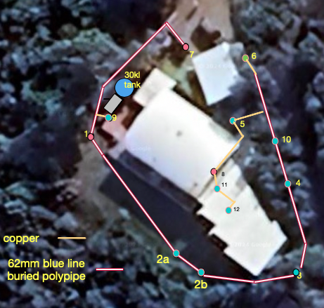
- Sprinkler 1, a VYRSA-60, has the double job of wetting the side as well as the deck front of the house. It is positioned at the steps on the west side of the house; the bottom of the sprinkler is 2 metres above the ground.
- Sprinklers 2a and 2b are two Pope sprinklers used here instead of a VYRSA-60, which would have needed to be 3.6 m above ground and would still have left the far bedroom wall needing supplementary spray. Mounted at 2.2 metres on the boundary, one a third and the other two thirds of the way along, they do an excellent job at their minimum operating pressure of 36 PSI, covering from the end bedroom to the middle living room window.
- Sprinkler 3 is a Pope which, at a height of 500 mm, produces a small segment of spray to protect the end of the house.
- Sprinkler 4 is a Pope at a height of 150 mm, keeping the side of the house wetted, including the windows.
- Sprinkler 5 is a Pope which, at a height of 100 mm, keeps the shed, gas bottles, and the north-facing door, deck and walls wetted.
- Sprinkler 6 is a Pope which, at a height of 100 mm, keeps the north wall of the shed wet.
- Sprinkler 7 is a VYRSA-60 which, at the north brush-fence entrance to the house at a height of 1.2 metres, wets the west and south of the shed, the north-facing door, deck and walls (overlapping the spray from 5), and the east deck (overlapping 1).
- Sprinkler 9, attached to the vacuum breaker post, wets the clerestory windows above the west side verandah roof.
- Sprinkler 10, at a height of about 2 metres, wets the first area of roof between sprinklers 8 and 11.
- Sprinklers 11 and 12 are both Pope heads mounted to wet the clerestory window sections of the east guest bedrooms.
To confirm: the older notes differ on which of sprinklers 9 and 10 is the third VYRSA-60 (one list gives 1, 7 and 9; the descriptions give 1, 7 and 10), and sprinkler 8 is not described.
Siting the sprinklers
The siting of sprinklers was determined by pre-planning, considering their rated spray radii, followed by testing. At each position a corresponding sprinkler was placed on a flexible moveable pole and fed by a rubber hose with tap water further pressurised by a small electric centrifugal pump. The positions were then experimented with at different heights, angles and positions to achieve optimum overall coverage.
This at least gave initial confidence as to the likely capabilities of the sprinklers, their minimum area of wetting, and the heights and positions to place them. Even after the feeder pipe and pump were operational and the posts established, the sprinklers were still initially connected by rubber hose so that their heights could be adjusted, and only when that was finalised were they plumbed in with copper pipe.
Hydraulics and balancing
The hydraulic design required careful analysis to ensure adequate pressure at all sprinkler locations, allowing for pipe friction and differences in height. Using the measured pump performance curve (about 50 metres head at 130 L/min and 45 metres at 300 L/min - see Water Infrastructure: tank, pump and feeder pipe), the calculations showed that even at the hydraulically most disadvantaged position, about 100 metres of 50 mm internal diameter pipe from the pump, the pressure remains adequate. Pipe friction in the DN50 blue-line pipe at 200 L/min is only 4.55 metres of head over 100 metres, and the sprinklers are nowhere more than about 5 metres above the pump. (In principle the pump's 70 metres of head means no water would flow at all 70 metres above it; the sprinklers must be lower than that by the pressure each needs to operate - comfortably the case here.)
Flow at each sprinkler is balanced with a brass ball valve on its riser, which prevents oversupply at the near sprinklers and undersupply at distant ones. With every sprinkler running, the system draws 147 L/min at reduced flow, rising to 217 L/min at high flow when the motorised valve diverts water around the flow restriction (both measured against the house water meter).
Copper risers and adjustable mountings
All fittings above ground outside the pump shed are in brass or copper. Each sprinkler is served by a copper riser (Type B copper pipe) from a saddle clamp with a brass compression fitting on the buried feeder pipe, rising underground to the brass adjustable sprinkler mount, with a brass ball valve for individual control. Pipe diameter follows the sprinkler's rated flow: 15 mm (1/2 inch) copper for the 10 L/min Pope sprinklers and 20 mm (3/4 inch) for the 20 L/min VYRSA units. Copper was chosen over plastic for its fire resistance, pressure capability and long service life, despite higher material costs and more labour-intensive installation requiring flaring tools and compression fittings.
The sprinkler mounts are designed to let the angle of spray be adjusted both vertically and horizontally, and the precise segment of spray is set at the sprinkler to suit the geometry of the area to be wetted. Each riser terminates in a flared compression fitting connected to a brass elbow with a male BSP thread. A second brass elbow screwed onto the first allows horizontal rotation for spray direction, with the sprinkler itself threaded onto this second elbow. Vertical angle is adjusted by loosening the compression fitting, rotating the whole elbow assembly, and retightening. This simple arrangement gives full directional control without any complex gimbals.
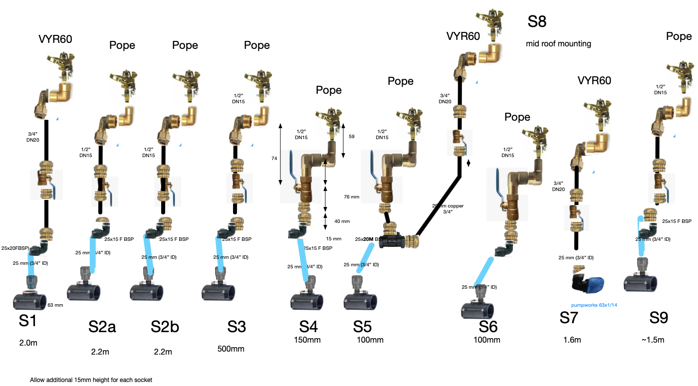
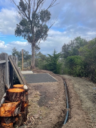
Sprinklers are mounted on treated pine posts concreted into position, ranging from 10 cm on the uphill side to 230 cm above ground on the downhill side, with the copper pipe clamped to the posts using standard copper tube clips. Additional height beyond the top of the post is achieved by extending with copper pipe as needed. The exposed copper, while industrial rather than concealed in appearance, is easy to inspect and repair and lasts indefinitely when properly supported.
Pipe materials and connections
The choice of pipe materials and connection methods reflects the conflicting demands of cost, fire resistance, ease of installation, and long-term reliability. Three material systems are used, according to location and function.
- Underground distribution - the 100-metre DN50 (63 mm OD) blue-line polypipe feeder, protected by its burial depth (see Water Infrastructure: tank, pump and feeder pipe). Its 63 mm outside diameter accepts saddle clamp fittings without cutting the pipe.
- Above-ground control and risers - all above-ground piping in the pump shed and every sprinkler riser is copper: DN50 for the main header, DN20 (3/4 inch) for the reduced-flow and recirculation branches, 12 mm for the shed cooling lines, and DN20 or DN15 for the risers.
- Hoses and flexible connections - short flexible sections use fire-rated reinforced silicone hose (maximum operating temperature 260 °C) rather than standard rubber hose, which would fail under radiant heat. The 400 mm connection from the pump exhaust to the shed wall penetration is DN40 high-temperature silicone, and the pump inlet uses DN50 wire-reinforced silicone hose with sleeve fittings. Standard rubber garden hose was explicitly avoided anywhere exposed to possible fire.
Connections. Flared brass compression fittings (no olive) were selected for all external copper runs, bearing in mind that joints must remain sound during direct fire exposure, not merely in normal operation:
- press fittings were rejected on cost and because they use a nylon or silicone seal, which is vulnerable to heat (the fire-rated version being even more expensive);
- soldered copper joints were rejected because lead-free solder softens well below bushfire-relevant temperatures and offers little strength once water flow (which provides cooling) is absent, for example during intermittent operation;
- silver-brazed joints, while thermally robust, are costly because of the silver content, and cannot be taken apart;
- grooved (Victaulic-style) mechanical couplings were considered for their tolerance of misalignment, particularly on larger pipe, but were excluded because their seal depends on an elastomeric gasket rated well below fire-exposure temperatures.
Flared fittings also serve in place of barrel unions, allowing pipe sections to be removed for maintenance. Where DN50 copper pipe was used, the ends were annealed with a MAP gas torch before flaring with a flaring block and pin, to prevent work-hardening cracks. At a few selected DN15 locations, standard compression fittings with copper olive inserts were used where cost-effective and appropriate. BSP thread connections are sealed with Teflon tape combined with Teflon paste.
Last checked: 7 November 2026. How the pipework choices were arrived at: Development history: sprinklers and pipework.
<< Water Infrastructure: tank, pump and feeder pipe | | The Water Control System: valves, flow modes and the pump shed >> |Table of Contents>