
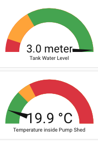
Dashboard displays (click to enlarge)
The sensor suite provides a range of environmental monitoring, with each sensor chosen for specific aspects of fire defence decision-making. All the sensors are read by Arduino AR2 in the Autonomous Module (Module 4), which broadcasts the readings by UDP over its own WiFi network to AR3; AR3 passes them on to AR1 over RS-485, and AR1 to Home Assistant. For current pin assignments refer to Arduino pin allocations.
Tank water level
For control of watering in cinder-protection low volume mode, the crucial question is how much water is being used from, and remains in, the water tank. The autonomous algorithm must know how much water remains to decide whether aggressive fire defence is sustainable or whether conservation must take priority.
Sensor. After difficulties with an RS485 water depth sensor, a QDY30A submersible level sensor with a stainless steel (SS304) probe was adopted. The unit installed is the QDY30A-B, a 2-wire 4-20 mA loop-powered transmitter with a 0-5 m range. It draws 4 mA at zero depth, rising linearly to 20 mA at 5 m. It was bought from QiDian Transmitter on AliExpress (5 m range, 10 m cable, 4-20 mA output). Its specification allows a temperature drift of up to ±2% of full scale, that is about ±10 cm.
Cable. The probe hangs on a 10 m vented cable, about 3 m of it submerged, sleeved in fire-resistant silicone and terminated in the pump shed. From the probe it rises over the top of the tank, drops to run along the recirculation pipe back to the tank (about 1.8 m above the ground) for some 5 m outside, then runs several metres inside the shed to AR2. The cable end is as supplied, with no joints. The cable carries a small vent tube which lets the sensor compare water pressure with atmospheric pressure. At the cable end the vent is a short, slightly thicker tube (red in the supplier's photograph) with no wire in it, cut off beside the red, blue, black and white wires. The vent end in the shed is fitted with a breather cap with a white filter, which lets air through while keeping out moisture and dust, and should be left on. The vent must be kept dry and unkinked - not taped, shrink-wrapped or clamped in a terminal or gland; a blocked vent traps air whose pressure changes with temperature and appears as a false change in depth.
Wiring (4-20 mA loop).
- +12 V (regulated) -> sensor red (+).
- Sensor blue (-) -> 235 Ohm shunt resistor -> green wire -> GND. The shunt is made from two resistors in series (measured 235 Ohm), soldered, with soldered joints to the sensor, A0 and GND wires.
- AR2 A0 reads the voltage across the shunt (AR2 GND common with the supply 0 V).
- In theory 4 mA gives 0.93 V and 20 mA gives 4.66 V across the shunt, which keeps the signal within the Arduino's 0-5 V input. At the tank's 3 m maximum the loop draws about 13.6 mA (about 3.2 V), comfortably within what a 12 V supply can drive.
  +12 V ----> sensor (+) red
              sensor (-) blue -----+----> AR2 A0 (black wire)
                                   |
                              [ 235 Ohm ]   (two resistors in series)
                                   |
  0 V / GND ------ green wire -----+----> AR2 GND
Bench test. Measured across the shunt: 0.95 V with the probe in air and 1.12 V at 0.24 m depth (about 0.71 V per metre). The readings were the same with 12 V and 24 V supplies.
Calibration against the house water meter. The conversion from voltage to depth was calibrated as follows:
- The tank was drawn down by a 10-minute sprinkler run and refilled through the house water meter: 1,520 L.
- Tank: corrugated cylinder, about 3.44 m internal diameter, so about 95 L per cm of depth. Internal height 3.08 m; full water depth 2.94 m (14 cm freeboard). Usable volume about 27,500 L.
- Resulting conversion in AR2: depth (m) = 1.513 x (V - 1.030), not allowed below 0. A full tank reads 2.94 m.
- This was first set with the original 240 Ohm shunt as 1.478 x (V - 1.254). When the shunt was rebuilt at 233 Ohm, and again when it was remade at 235 Ohm, the scale was adjusted in proportion and the zero point reset so that the full tank still reads 2.94 m. Just after AR2 restarts the reading has been seen to run about 0.05 V (about 8 cm) high for some hours before settling, so the zero point is set from the settled reading.
- The scale (1.478 m per volt on the original shunt) agrees with the bench test (about 1.41 m per volt) within that test's accuracy.
- The zero point (1.030 V) is uncertain to about +/-15 cm and could be refined with a larger metered refill (about 4,500 L would give about +/-5 cm). It differs from the bench "in air" reading (0.95 V on the original shunt, about 0.92 V on the present one) by about 0.11 V (about 17 cm); the cause has not yet been identified.
Glitch filtering. Ten days of Fairhaven readings showed brief jumps of 10-20 cm, mostly lasting a single 2-second report, almost all between 8 am and 7 pm, and unrelated to wind, rain or humidity. They are electrical noise on individual analog readings, measured against the Arduino's own 5 V: one ADC step is about 0.7 cm of water, so a disturbance of about 70 mV on a single sample appears as a 10 cm jump. AR2 therefore:
- takes the median of 9 quick samples (spread over about 2 ms) for each reading, and
- reports the median of the last 5 seconds of readings.
Real level changes are slow (about 1.5 cm per minute with the pump running flat out), so the 5-second delay is immaterial. Simulated on the ten days of Fairhaven data, the filter removed about 70-85% of the jumps while keeping the real drop of a pump run; on TestSys the wobble fell from 0.70-0.76 m to 0.71-0.73 m. Also worth checking on site: the shunt's ground should run directly to AR2 GND beside A0, and a small RC filter at A0 (10 kOhm in series, 0.1 uF to GND) would further smooth supply ripple.
Planned: low-water float switch. A stainless float switch changing over at 0.30 m true depth, read by AR2 on D7, will give AR3 an independent signal for the gel-priority decision, with a plausibility check against the analog level.
Data path. AR2 A0 -> AR2 UDP (WATER_LEVEL) -> AR3 -> AR1 (RS-485) -> MQTT home/sensor/water_level -> Home Assistant "Water Level" (sensor.water_level), shown to 0.01 m.
If the gauge fails. A reading below 0.9 V (cable cut or sensor dead) or above 4.6 V (short circuit) for 2 seconds is treated as a failed gauge. AR3 then estimates the level from the flow meters, so that a cut cable is not mistaken for an empty tank (see Autonomous Fire Defence Algorithms).
Temperature
Three DS18B20 digital temperature sensors ($0.56 each), on a common 1-Wire bus on AR2 pin D7 with a net terminating resistance of 2.4 kOhm, measure the shed and external temperatures: one inside the shed, one outside, and a second outside sensor whose metal tip protrudes through the shed wall. The 1-Wire protocol allows multiple sensors on a single data line, each identified by the unique 64-bit address burned into it during manufacture. The code binds each address to its function, so a sensor's identity follows its hardware rather than its position on the cable:
- 28 2E 53 57 00 00 00 3E - outside
- 28 11 F1 35 00 00 00 D0 - inside the shed (identified on site by warming each probe in turn)
- 28 5B 83 57 00 00 00 13 - outside 2
The sensors operate at 12-bit resolution (0.0625 °C), with a reading roughly every 750 ms. The 1-Wire bus needs careful timing and is susceptible to electrical noise, so AR2 checks every reading. A sensor that does not answer, gives a value outside -55 to +125 °C, or reads exactly 85 °C (the value these sensors give after a power glitch, unless it was already reading close to 85 °C) is treated as failed. AR2 then sends 0 for that sensor, so that it stands out on the dashboard, together with a failure flag; AR3 acts on the flag, never on the 0 - which matters because 0 °C can be real on a winter night, and a sudden drop to 0 would otherwise look like the fire passing. If all three sensors fail on five consecutive readings, AR2 resets and reinitialises the bus, which recovers from a voltage transient or electromagnetic pulse (from lightning, for example) without manual intervention. All three sensors tend to drop out together for a moment when the diesel is cranked, as the 12 V supply dips. So if all three fail, or fall below half their last value, in the same reading, AR2 keeps sending the last good values for up to 10 seconds, or until all three read normally again; only if they have not recovered by then is the failure reported. What Autonomous mode does when sensors fail is described in Autonomous Fire Defence Algorithms.
Water flow
Water flow is monitored with two Hall-effect turbine flow meters, plus a visual flow meter and pressure gauge in the shed's control pipe for manual checks. Each meter contains a small turbine with a magnet; a Hall-effect sensor detects each passage of the magnet, giving one pulse per turn, so the pulse rate is proportional to the flow.
- The DN50 meter on the pump output line (BSP thread; wiring red +V, yellow signal, black ground; 5-18 V DC) measures the water actually going to the sprinklers and shed sprays, since it sits after the recirculation valve. Its calibration, 16.2 pulses per litre, was set against the house water meter. The meter is powered from a clean 5 V supply, separate from the Arduino's, since noise on the Arduino's 5 V rail produces phantom flow readings.
- The DN15 meter on the mains feed to the tank gives about 450 pulses per litre, as calibrated by the manufacturer.
The meters connect to AR2's interrupt-capable pins (D2 and D3), so pulses are counted the moment they arrive without the main program having to poll them. The interrupt routines apply an 8-millisecond debounce, only counting a pulse if enough time has passed since the last, so that vibration or electrical noise does not cause false counts. Several times a second the main program reads and clears the accumulated counts - briefly disabling interrupts so that a pulse arriving mid-read cannot be lost - and converts them to litres per minute. For the DN50 meter the figure sent is the average over the last 2 seconds, because a tenth of a second holds only a few of its pulses and on its own would make the reading jump by about 37 L/min at a time. Flows below 0.05 L/min are set to exactly zero, to eliminate noise from stray pulses.
Real-time flow monitoring turned out to be less important than originally supposed: the visual flow meter confirms that flow rates are stable and predictable, and the tank level sensor gives the crucial information of how much water remains. The flow readings come into their own if the tank gauge fails, when AR3 uses them to estimate the remaining water.
Oil and water pressure: shared switches, diode protection and the optocouplers
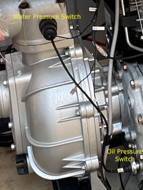
Oil and water pressure switches installed (click to enlarge)
Two pressure switches on the pump are required by the pump control module, and are also read by AR2, giving assurance that the diesel pump really is running and delivering water. Together they distinguish mechanical failure (oil pressure present but no water pressure, pointing to a pump or valve problem) from engine failure (no oil pressure). How the water pressure switch was fitted, by drilling and tapping the pump casing, is described in Output Control and Safety Interlocks.
The pump engine has two pressure switches. Each is a single-terminal switch that connects its wire to the engine block (GND) when closed:
- Oil pressure switch: closed (to GND) when there is no oil pressure. It opens once the engine is running and oil pressure builds.
- Water pressure switch: open when there is no water pressure. It closes once the pump develops water pressure, about 20 s after starting.
Each switch is read by two separate systems:
- The SFS01 Control Box: oil on input W3, water on input W4. The box uses the oil pressure input to recognise that the engine has started (and to stop cranking), and the water pressure input to send its "pump started" SMS.
- ARMAC, through Arduino AR2: oil on D10, water on D13. These readings appear in Home Assistant and are available to the Autonomous Module.
The single wire from each switch is therefore split. One branch runs to the Control Box and the other to an optocoupler on the ARMAC opto board.
Why the ARMAC branch must not load the Control Box
The Control Box senses each switch by placing its own small voltage on the switch wire and watching for the switch to pull it to 0 V. With the switch open, the box holds about 4.0 V on W3 (oil) and about 2.95 V on W4 (water).
If an optocoupler input were connected directly to these shared wires, its LED would give the box's sensing current a path to ground and drag the box's voltage down. With the engine running and the oil switch open, the box would then see what looks like zero oil pressure, conclude that the engine had not started, and re-engage the starter on the running engine about every 20 seconds. ARMAC's branches are therefore isolated from the box's sensing circuits as follows.
A diode and a pull-up resistor on each ARMAC branch
On each ARMAC branch, after the split from the Control Box wire:
- A 1N5819 Schottky diode is fitted in series, mounted close to the switch, with its band (cathode) towards the switch and its other end towards the opto IN terminal.
- A 1 kOhm resistor runs from the 5 V rail to the opto IN terminal, mounted close to the opto board. Each opto has its own resistor; a single shared resistor would join the two signals together.
How it works:
- Switch closed: current flows from the 5 V rail through the 1 kOhm resistor and the diode into the switch and to ground. The switch pulls the opto IN terminal down to about 0.3 V (the diode's forward drop), so the opto's LED is off.
- Switch open: the 1 kOhm resistor pulls the opto IN terminal up to 5 V, so the opto's LED is on.
- The diode only lets current flow towards the switch. The Control Box's current cannot leak away through the opto LED, so the box's sensing voltages are not pulled down, and the box sees its switches as if ARMAC were not connected. (With the switch open a small current can pass through the diode into the box input, but that only holds the line high, which is the "switch open" reading the box expects.)
- The optos take their drive from ARMAC's own 5 V rail rather than from the box. ARMAC therefore reads both pressures even with the Control Box disconnected, which will be needed if ARMAC later takes over starting the pump itself.
  Pressure switch (closes to engine GND)
        |
        +--------------------------------> Control Box input (W3 oil / W4 water)
        |
     1N5819   (band at the switch end)
        |
        +------[ 1 kOhm ]------ +5 V rail
        |
   OPTO IN (bottom terminal)        OPTO IN common (top terminal) --> GND

   OPTO OUT terminals:  bottom = +5 V rail   middle = OUT --> AR2   top = GND
The optocoupler board
Both optos are on one two-channel board: OPTO 2 = oil and OPTO 1 = water.
- Input side (each opto): the bottom terminal takes the signal from the diode / 1 kOhm junction. The top terminal is the input common, shared by both optos, and is grounded.
- Output side (each opto): the bottom terminal is +5 V from the 5 V rail, the middle terminal is OUT to AR2, and the top terminal is GND. OUT is pulled LOW when the opto's LED is on.
- Oil (OPTO 2) OUT -> AR2 D10 (digital). Oil pressure present = switch open = LED on = D10 LOW. HA shows "Pump Oil Pressure High".
- Water (OPTO 1) OUT -> AR2 D13 (read as a digital input and reported as 0 or 5 V). About 0 V with no pressure and about 4.8 V with pressure. HA shows "Pump Water Pressure" ON above 2.5 V.
- All grounds (the opto input common, the opto output GNDs, AR2 and the 5 V rail) are common. The board therefore acts as a buffer and level converter rather than providing full electrical isolation.
The shared input common (top IN terminal) and each opto's output GND (top OUT terminal) must be connected to ground; if either is left floating the readings fail (an unconnected output GND on OPTO 1 prevents the water pressure from registering at all).
Battery voltage
The shed battery's voltage is read by AR1 in the house. Module 2 is powered from the shed battery, and a resistor divider takes its fused 12 V supply down to AR1 pin A0: 30 kΩ from the supply to A0, and 10 kΩ with 100 nF across it from A0 to GND, so about 3.3 V at 13 V. AR1 multiplies by 4 and applies a trim set against the Victron display, which also allows for the small drop between the battery and the module. A reading taken while AR1 is powered from a computer's USB is not valid, because AR1 measures against its own 5 V supply.
AR1 samples the voltage 50 times a second. It publishes Battery (AR1), smoothed over about 10 seconds, and passes it to AR3 in its status messages (as BAT:). When the voltage falls more than 0.4 V below its normal level for half a second or more, as when the starter cranks, AR1 records the lowest voltage and how long the dip lasted. Shorter blips are ignored.
AR2 also has a battery divider, on pin A2, but it reads full scale: it shows 13.24 V whatever the battery is doing, until its divider is corrected. Its reading is still shown for comparison but is not used.
Because battery voltage can fluctuate rapidly with load - particularly when the diesel starter motor draws perhaps 200 amperes - AR2's measured voltage passes through an exponential moving average filter with a 45-second time constant: Vfiltered(new) = Vfiltered(old) + α × (Vmeasured − Vfiltered(old)), where α = dt/τ, dt is the time since the last update, and τ is 45 seconds. After 45 seconds about 63% of a step change in actual battery voltage has come through, giving good noise rejection while still tracking real changes over the hours of a fire event. The filter starts from the first real reading rather than from zero.
Diesel fuel level
When it was decided to add a larger diesel tank, the decision was also taken to fit an electronic fuel depth sensor to supplement the manually read fuel gauge, to be read on AR2 pin A3, shown on the Home Assistant dashboard as a gauge card, and available to the decision making. The choice was a 12 V, 100 mm Wema 240-30 ohm float sender, read with a fixed reference resistor (from Boat Accessories Australia). It uses magnetic reed switch technology with a moving float, is made in 316 stainless steel and is suitable for diesel. An empty reading still leaves about 35 mm of fuel in the tank.
The sender is wired 5 V - 100 ohm resistor - sender wire 1 ... sender wire 2 - GND, with wire 1 also connected to AR2 pin A3. This divider draws an acceptable 9-15 mA. Bench testing showed 3.54 V when empty and 1.17 V when full, and a calibration run on AR2 gave raw readings of 258 (full) and 788 (empty), which the code uses. The sender covers about 35-135 mm above the tank floor.
The sender is fitted in the 24-litre reserve fuel tank, which is installed in parallel with the pump's 13-litre tank (see Water Infrastructure: tank, pump and feeder pipe). This tank is 135 mm deep with its outlet at the very bottom, so the sender reads full when the tank is full, and when it reads empty about 6 litres still remain in this tank alone.
Ember detection
Embers are detected by a 3-wire 5 V infrared flame detector module (760-1100 nm, 80 cm detection distance, $2.83 from AliExpress), mounted inside a 100 mm stainless steel chimney cowl for weather protection, on a 100 mm round end cap with a 3 mm rebate (cowl and base $27 including shipping). The base is packed with paraffin-infused wood wool, which is easily ignited by an ember of enough thermal output to endanger the house. Since this is an advance warning system it can be connected by above-ground wires to AR2 (digital input D12), and it is reported via RS-485 from the pump shed to the Remote Control Module and so to Home Assistant, where it raises an alert. It does not by itself start the sprinklers.
The problem with this approach is the uncertain sensitivity of the detector in changing light, temperature and wind. (It would be possible to back it with an MLX90640ESF-BAA infrared camera module - a 32 × 24 pixel array covering -40 °C to 300 °C over a 100 × 75 degree field of view at up to 3 metres, about $54 from AliExpress - but at this stage that was not felt to add enough information to be justified.)
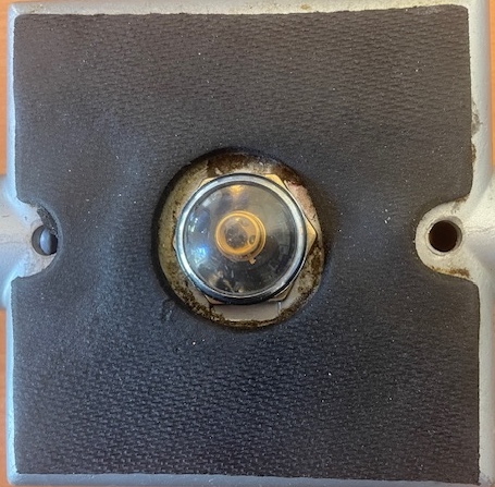
Pyrotector ember detector (click to enlarge)
More recently another approach has begun which is more complex, but more likely to work reliably. It uses an industrial Pyrotector Model 30-2054 glowing-ember detector (labelled Chloride Pyrotector, Hingham MA; the Pyrotector brand belongs to Detector Electronics Corporation). This is designed to detect embers over a broad range of speeds: for example, a 0.6 cm (1/4 inch) ember is detected at up to 23 cm when moving at 13 cm/sec (0.5 km/hr), or up to 76 cm at 48 m/sec (174 km/hr). The more sensitive 30-2054A reaches about twice as far. The detector is made in 12 V and 24 V versions; which this one is has still to be confirmed (a 24 V unit is easily supplied by a step-up module from the 12 V supply). The unit purchased (US$66 plus postage, used) is quite old but works well on test. It must work in light of less than 100 lux, so it is planned to install it on the lid of an aluminium box fed by four 150 mm stormwater pipes laid out like a pinwheel, each ending in a bend that blocks the light, which carry wind - and embers - past it from any direction (see Ember detector (planned)).
Video camera
A 360-degree WiFi video camera ($17 from Temu, 5 V DC), mounted outside the pump shed on the vacuum breaker post, has enough WiFi connectivity to give a good remote picture of smoke and fire. It can be manoeuvred to look around, and will be sacrificed if the fire front arrives (see Camera and apps).
From the sensors to the dashboard
AR2's main program reads all the sensors in turn: it requests temperature conversions from the three DS18B20 sensors, and while they convert it reads the tank level, battery voltage, oil pressure and water pressure. All the values are then assembled into a single line of pipe-delimited key-value pairs - for example EXT_TEMP:35.20|INT_TEMP:30.15|EXT2_TEMP:35.20|FLOW_IN:0.00|FLOW_OUT:165.30|FLOW:165.30|EMBER:0|WATER_LEVEL:2.85|BAT:13.20|OIL_OK:1|WATER_PV:4.80, together with the sensor failure flags - and broadcast to IP address 255.255.255.255 on port 5000, reaching every device on AR2's WiFi network. AR3, connected to that network, listens on port 5000, extracts each value by its key, and stores it for the autonomous control algorithms. The whole cycle of reading, broadcasting, receiving and parsing completes in well under a tenth of a second, giving effectively real-time data to the decision-making code.
The shed display
For testing and operational assurance in the shed, it is important to be able to see easily what the system is doing. Arduino AR3 is therefore equipped with a two-line LCD display (LiquidCrystal_I2C, address 0x27) on its I²C pins, in the Autonomous Module. It cycles through three pages, 2.5 seconds each: water level and mode, the heartbeat from the house, and the state of the pump and the four electronically controlled valves.
Last checked against the code: 7 November 2026. Earlier sensors and wiring: Development history: sensors.
<< Battery, charging and power distribution | | Ember detector (planned) >> |Table of Contents>