
Status: designed, not yet built. The ember detector in use today is the infrared flame sensor described in Sensors; it raises an alert only.
Purpose
The aim is to detect airborne glowing embers arriving at the house early in an ember attack, before spot fires develop, using the industrial Pyrotector 30-2054 high-speed glowing-ember detector already held (see Sensors and its instruction manual), and to report each detection to the ARMAC AR1 controller.
The Pyrotector responds to infrared radiation between 1 and 3 microns, but it must work in light below 10 foot-candles (about 108 lux) - sunlight sets it off. So its housing has two jobs: to carry wind-borne embers past the detector from whatever direction the wind is blowing, and to keep daylight off its lens.
The design: a four-pipe pinwheel box
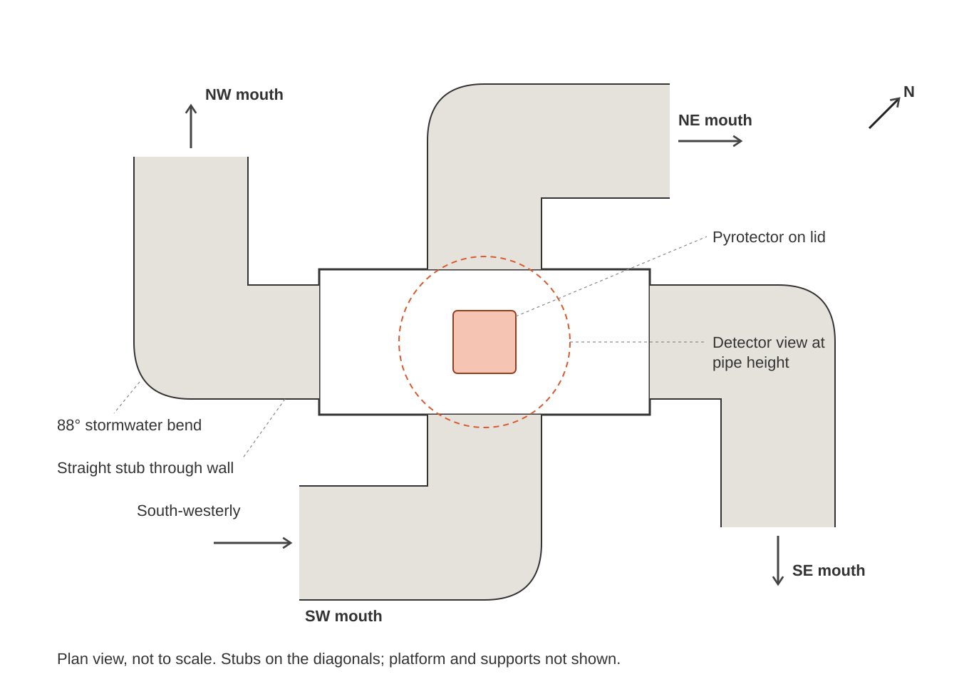
Figure 1. Plan view of the pinwheel box (click to enlarge)
An aluminium box (465 × 205 mm in plan, 270 mm deep) carries four 150 mm PVC stormwater pipes, one through each side wall. Each pipe passes straight through the wall and then, outside the box, turns through a standard 88° stormwater bend laid on its side, so that its mouth faces along the wall. The four mouths face four different directions, like a pinwheel.
Whichever mouth faces the wind receives nearly the full wind pressure, while the other three sit in suction and act as outlets. Air and embers therefore enter through the windward mouth, pass through the box and leave through the others - from any wind direction, and with no moving parts.
Inside the box the opposite stubs are in line, and the two pairs cross at the centre, directly beneath the detector mounted on the lid. So whichever pipe is the inlet, the main stream of air and embers passes under the lens, about 135 mm below it.
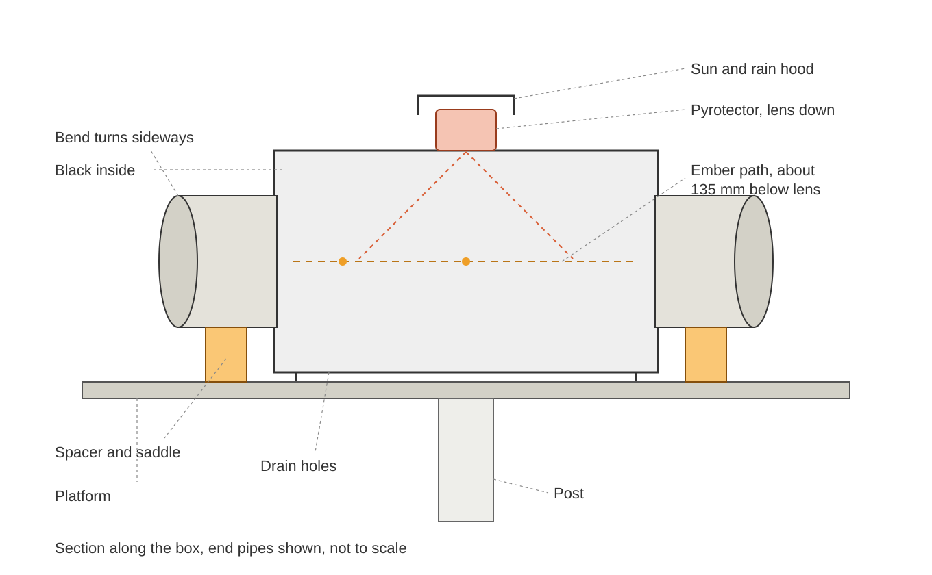
Figure 2. Section along the box, showing the detector and the ember path (click to enlarge)
The design has several advantages. There is no swivel, vane or slip ring to wear or stick. Each 88° bend leaves no straight line of sight into the box, so light can only get in by reflecting off the black inside of the bend. And it uses the existing box and standard stormwater bends, with few or no glued joints.
Other arrangements were considered and rejected. Straight pipes without bends would be simplest, but low sun shining straight along a pipe leaves only a small margin against the light limit. Elbows turned down inside the box will not fit - a 150 mm elbow is too big for the 205 mm width of the box - and a 45° elbow does not block the line of sight. PVC pipes are used since ember detection is required well before a fire front arrives and by the time the pipes are affected by heat the temperature rise itself will be the primary basis of decisions on system settings.
The trade-off. Embers do not follow the bend. Each strikes the outer wall of the bend once and is then carried on into the box by the airflow. Some break up, but the fragments still glow, and the larger embers that can ignite a house are the most likely to survive. In a real ember attack embers arrive in numbers, so losing a fraction at the bend does not prevent detection. A slight fall towards the box lets embers slowed at the bend roll inward. Long-sweep bends would be gentler on embers, but are much larger and dearer; standard bends are used for compactness and cost.
Where it goes
On the device. The detector sits centred on the lid, lens facing down, directly above the point where the four stubs cross. The lid needs a 28.6 mm (1-1/8 inch) lens hole, with two 6.35 mm (1/4 inch) bolt holes 88.9 mm (3-1/2 inch) apart, one either side. The detector body stays outside the box, and its full-face neoprene gasket must seal against a flat surface - if the lid is ribbed or embossed, a small flat aluminium plate is fitted under the detector and sealed to the lid. A sun and rain hood about 20 mm above the detector keeps its housing below its 65 °C rating in summer sun and keeps rain off the conduit entries. Lifting the lid gives access for inspecting and cleaning the lens (spiders, dust and soot).
On the site. The box goes on a post at about mid-height of the house - the zone that embers strike when they reach walls, eaves and nearby combustibles - and clear of walls, buildings and trees by at least the width of the device, so that all four mouths see the wind. It is turned so that the stubs lie on the diagonals and the mouths face NW, NE, SE and SW. The dangerous north-westerly and south-westerly winds then meet a mouth head-on, and the pipes are kept away from the bearings of the low sun in the fire season (roughly ESE at sunrise and WSW at sunset). It also needs to be within practical cable reach of AR1, and somewhere it can be reached safely for inspection.
The detector
The figures relied on, from the Pyrotector instruction manual (95-8363-01):
| Parameter | Value |
|---|---|
| Operating voltage | 12-16 V DC (12 V unit), 20-27 V DC (24 V unit) |
| Operating current | standby 12 mA maximum, alarm 70 mA maximum |
| Relay output | dry Form C (SPDT), 1 A at 26 V DC |
| Spectral range | 1.0-3.0 microns, peak 2.5 microns |
| Response time | 8 ms average |
| Ember size and speed | 1/16 to 5/16 inch, 25 to 10,000 ft/min |
| Detection distance (1/4 inch ember) | up to 24 inches (30-2054), up to 54 inches (30-2054A) |
| Cone of vision | 90°, 75% sensitivity at 45° off axis |
| Ambient light | below 10 foot-candles; sunlight and incandescent light cause false alarms |
| Temperature range | -25 °C to +65 °C |
| Lead colours | red +V, black 0 V, white relay common, blue NC, orange NO |
The ember path lies about 135 mm below the lens, well within the detection distance, and at that depth the detector's view is about 270 mm across, covering the crossing point of the four stubs. Embers slowed by the bend and the box are still well within the specified speed range: an ember crossing the view at 5 m/s is in sight for about 50 ms, against the 8 ms response time.
Keeping the light out
Because each bend blocks any direct line of sight into the box, daylight must reflect at least once off a black surface before it can get in. Rough estimates of the light reaching the lens:
| Situation | Light at the lens | Against the 108 lux limit |
|---|---|---|
| Daylight, interior matte black | well under 5 lux | large margin |
| Low sun shining into a mouth, interior matte black | about 1-3 lux | large margin |
| Any bare aluminium or grey PVC inside | many times higher | likely to fail |
Paint is essential. Bare aluminium reflects about 90% in the infrared. The aluminium gets an etch primer, then a flat black, carbon-based paint inside the box, under the lid, and inside every stub and bend. IR-reflective ("cool") black paints must be avoided. These figures are estimates, and the field test (below) decides; if stray light does prove a problem, a short black tube around the lens will narrow its view to the crossing point.
Construction
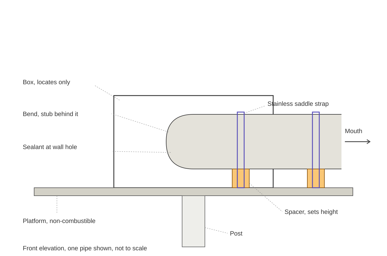
Figure 3. Pipe fixing: platform, spacers and saddle straps carry the pipes (click to enlarge)
The principle is that the thin aluminium box only locates the pipes and seals the holes. All the weight and wind load is carried by a platform under the box, so nothing is glued to the box and its walls carry no load.
The box. A snug 162-163 mm hole is cut in the centre of each side wall, centred at mid-height (about 135 mm) - with plywood clamped firmly behind the wall and a 160 mm holesaw cutting through both, or with a fine metal jigsaw blade and filed to the line. The lid is drilled for the detector, a few 6 mm drain holes are drilled in the floor away from the centre, and the inside and the underside of the lid are etch-primed and painted flat black.
The pipes. Four standard 150 mm 88° PVC stormwater bends (160 mm outside diameter pipe size) are used. Male-and-female (M-F) bends are preferred: if the spigot end is long enough to pass through the wall and project 10-20 mm inside, it goes straight through the hole and no separate stub, pipe or glue is needed (the spigot length is to be checked in the store). Otherwise female-and-female bends are used, each joined with PVC primer and solvent cement to a short stub of 150 mm stormwater pipe that passes through the wall. The bends are turned sideways to form the pinwheel, painted flat black inside, and given a slight fall towards the box, so that embers that slow at the bend roll inward and rain drains into the box and out through the floor drains. Stainless or aluminium bird mesh of 20-25 mm over each mouth keeps out birds and large leaves while passing embers.
Fixing. A flat platform on the post top - 9 mm compressed fibre-cement sheet or an aluminium angle frame, probably about 0.9 × 0.7 m (to be measured from the bends actually bought) - sits under the box and all four bends, and the box is bolted to it through the floor, clear of the drain holes. Spacer blocks under each bend, near the wall and at the mouth end, bring the pipe up to the hole height (about 55 mm) and are trimmed to give the fall towards the box. Stainless pipe saddles over each pipe, screwed through the spacers into the platform, carry all the weight and wind load. At the wall, MS polymer sealant (Sikaflex or similar) around each pipe seals out light and rain while staying flexible enough to take the different expansion of PVC and aluminium - there is no glue or clamp at the wall. The platform is fixed to the post with a galvanised post-top bracket or angle brackets.
Wiring
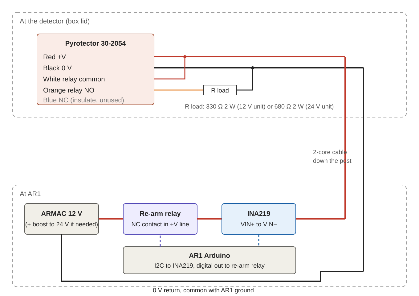
Figure 4. Two-wire signalling from the detector to AR1 (click to enlarge)
Only two wires run from the detector to AR1. When the detector sees an ember, its alarm relay switches a load resistor across its own supply, so the current it draws jumps; AR1 watches that current. At the detector the leads are connected as follows:
| Lead | Function | Connect to |
|---|---|---|
| Red | +V supply | +V conductor |
| Black | 0 V | 0 V conductor |
| White | relay common | red (+V) |
| Orange | relay normally open | load resistor, then black (0 V) |
| Blue | relay normally closed | not used; insulate |
The load resistor is 330 Ω 2 W for a 12 V unit or 680 Ω 2 W for a 24 V unit, and on alarm it adds about 35-48 mA to the supply current. The connections are made in a small weatherproof junction box beside the detector on the lid (or inside the detector housing if there is room), and the cable enters the detector through a 1/2 inch cable gland in one of its conduit entries and runs down the post to AR1. With no rotating joint, no slip ring or ride-through capacitor is needed.
At AR1 the detector is supplied from the ARMAC 12 V supply (through the 12-24 V boost converter board already held, set to 24 V, if it is a 24 V unit). The supply passes through the normally closed contact of a re-arm relay, so the detector stays powered even if the Arduino fails; energising the relay cuts the power to reset the detector. It then passes through an INA219 current sensor (VIN+ from the re-arm relay, VIN- to the +V conductor; VCC, GND, SDA and SCL to the Arduino), whose 26 V supply-side limit a 24 V unit run at 24 V respects. The 0 V conductor returns to the supply 0 V, common with AR1 ground. The Arduino pins are to be assigned in the AR1 sketch.
How it works
Wind enters the mouth facing it, turns through the bend and passes along the stub into the box, and the other three pipes carry the air out. Embers strike the bend once, are carried on by the airflow, and cross the box beneath the detector. A glowing ember in the detector's view is detected within about 8 ms: the detector's red LED lights and its alarm relay closes, connecting the load resistor across the supply, and its own current rises from standby to alarm. The detector is believed to latch in this state until its power is removed (to be confirmed on the bench).
Signalling and supervision. AR1 reads the INA219 continuously. Suggested thresholds, to be set from the values measured at commissioning:
| State | Supply current | Meaning |
|---|---|---|
| Normal | near the measured standby (12 mA or less) | armed, no ember |
| Alarm | standby plus at least 25 mA, held for 50 ms or more | ember detected, detector latched |
| Open circuit | below about 3 mA | broken wire or failed detector |
| Short or overload | above about 150 mA | wiring fault |
| Supply fault | bus voltage outside the detector's range | supply or converter problem |
Re-arming. On an alarm, AR1 records the event (time and count) and publishes it to MQTT. After a short hold (say 5 seconds) it energises the re-arm relay for at least 1 second (the minimum to be confirmed on the bench), then releases it and ignores the current reading for about half a second while the detector powers up. The detector is then armed again, and the cycle repeats for each ember.
Persistent embers. Some embers will settle on the floor of the box and keep glowing in view, so the detector will re-trigger as soon as it is re-armed. If the alarm returns within about a second of re-arming on several successive cycles, AR1 flags "ember in box", counts it as one persistent event rather than many embers, and lengthens the re-arm interval (for example to 30 seconds) until the re-triggering stops.
Response. A single detection may be a stray spark or a false trigger, so AR1 acts on the ember rate - for example new embers per minute over a rolling window - combined with the fire-danger state and the other ARMAC sensors, to escalate from monitoring to wetting to full defence. The thresholds are to be set in the AR1 sketch.
Parts and cost
| Part | Specification | Source | Estimate (A$) |
|---|---|---|---|
| Box | aluminium box, 465 × 205 × 270 mm | already held | 0 |
| Bends | 4 × 150 mm 88° PVC stormwater bends, M-F preferred | Bunnings or plumbing supplier | 60-120 |
| Stub pipe and cement | only if F-F bends are used: short length of 150 mm stormwater pipe, primer and cement | Bunnings or plumbing supplier | 0 (M-F) or 50-80 (F-F) |
| Paint | etch primer and flat black (carbon-based) | hardware store | 40 |
| Sealant | MS polymer (Sikaflex or similar), 1 cartridge | hardware store | 15 |
| Bird mesh | stainless or aluminium, 20-25 mm | hardware store | 15 |
| Platform | 9 mm compressed fibre-cement sheet (about 0.9 × 0.7 m) or aluminium angle frame | hardware store or building supplier | 30-50 |
| Spacers | hardwood blocks, about 55 mm | offcuts | 0-10 |
| Saddle straps | 8 saddles for 160 mm pipe, stainless or galvanised | plumbing supplier | 20-60 |
| Post bracket and fasteners | galvanised post-top bracket, stainless bolts and screws | hardware store | 30 |
| Junction box and cable gland | small IP65 box, 1/2 inch gland | electrical supplier | 15 |
| Current sensor | INA219 breakout module | Core Electronics or AliExpress | 10 |
| Re-arm relay | 5 V relay module (NC contact used) | Core Electronics or AliExpress | 5 |
| Load resistor | 330 Ω 2 W (12 V) or 680 Ω 2 W (24 V) | electronics supplier | 1 |
| Cable | 2-core outdoor | already held | 0 |
| Boost converter | 12-24 V, only needed if the detector is a 24 V unit | already held | 0 |
| Total | about 240-360 (M-F), 290-440 (F-F) | ||
All prices are estimates. The bends are the largest item, and M-F bends avoid the stub pipe and cement altogether; any suitable bends, sheet or offcuts already held reduce the total.
Maintenance
Before each fire season: open the lid, clear leaves and debris, check the mesh, clean the lens and check that the drain holes are clear; look for spiders and wasps in the pipes and box; check the sealant at the wall holes and the saddle straps; and run the soldering-iron test (below) to confirm detection and reporting at AR1.
Commissioning
- Latching (on the bench, before assembly): power the detector, pass a 40 W soldering iron or a lit cigarette quickly across the lens, remove it, and confirm that the LED and relay stay on until the power is removed. Also find the minimum power-off time that resets it. If it does not latch, the sensing must capture brief pulses (a hardware interrupt or comparator) rather than polling.
- Currents: record the standby and alarm currents with the load resistor fitted, and set the AR1 thresholds from them.
- Sensitivity in place: with the device assembled, pass the soldering iron through the crossing point and confirm detection and reporting at AR1.
- Airflow: using a leaf blower as the wind, at the mouths and at 45° between them, hold a smoking incense stick at each mouth and confirm that air flows in at the windward mouth and out of the others.
- Embers: with the blower running, feed sparkler sparks or smouldering charcoal fragments into the windward mouth; confirm detection, and note where embers settle.
- Daylight: with the device in its final position and orientation, log detector triggers at AR1 over several sunny days, including sunrise and sunset. There should be none.
- Persistence: leave a glowing fragment on the floor, and confirm that AR1 flags it as a persistent ember rather than counting repeated embers.
- Rain: hose the device down; confirm that water drains out, the lens stays dry and no leakage current appears.
- Supervision: disconnect one conductor and confirm that AR1 reports an open-circuit fault.
Still to be settled
- Confirm the latching behaviour and minimum reset time on the bench (believed to latch).
- Confirm from its label whether the detector is the 12 V or the 24 V unit.
- Check the lid is flat enough for the detector gasket, and add a flat plate if not.
- Obtain the bends (M-F if the spigot is long enough), measure them, then set the platform size and spacer heights.
- Assign the Arduino pins and write the INA219 sensing, re-arm and persistent-ember code for AR1.
- Choose the post position on site.
Earlier designs for the housing - a vane-mounted duct on a swivel, a version with long-sweep bends, and a two-box windcatcher with an internal funnel - are described in Development history: sensors.
<< Sensors | | The Electronic Control Sub-System >> |Table of Contents>