
How the tank, pump and feeder pipe came to be as they are. The present arrangement is described in Water Infrastructure: tank, pump and feeder pipe.
Planned and final layout of the pump connections
The pump comes with 3" outlets and corresponding hose tails. On the basis of performance curves for the pump the inlet and outlet were ultimately reduced to 2" utilising brass/stainless steel reducers.
Planned:

Final:

Placing the tank on its crushed rock bed (view towards the house):

The original estimates
The tank, a 30.3 kL unit from gettanked.com.au ($5,850 delivered), was planned on a nominal reduced flow of 170 L/min: sufficient for 3 hours and 8 minutes of spray, or up to, say, 10 hours in low-flow intermittent modes. The planning figures gave a total low-flow capacity of 2.8 hours together with a provision of 18 minutes at high pressure for when the fire front is present - overall 3.1 hours at full flow. Measured against the house water meter in October and November 2026, reduced flow turned out to be 147 L/min and high flow 217 L/min, and the usable tank volume about 27,500 L, giving about 3 hours of continuous reduced flow or 2 hours of high flow (see Water Infrastructure: tank, pump and feeder pipe).
The original tank specification listed an ultrasonic level sensor mounted at the top of the tank; it was replaced by the submersible pressure sensor now in use (see Sensors).
Extending run-time and water service time
I considered (1) extending the time that the system can run with either an electrically pumped fuel top-up system, (2) allowing the system to be run only intermittently or (3) fitting a larger tank. In the end I opted for (2) and (3).
A 24 l tank was available for $40 (with free delivery - an almost impossible bargain since you can pay $70 - $258 (delivered) for one on Amazon). To avoid any danger of fuel running out from the originally provided 13 l tank, this 24 l tank was to replace the original - giving a running time of some 15-20 hours. (In the event the pump would not run properly from it as a direct replacement, so it is instead to be mounted in parallel with the original tank - see Water Infrastructure: tank, pump and feeder pipe.) Since it is a petrol tank it was necessary to braze an additional 5/8" brass nozzle into the tank for the return line from the diesel injector unit. This was done using a MAP gas torch, a $64 57% silver brazing rod (from Hamdon Industrial P/Ltd) and a $13 pot of Tradeflame silver brazing flux from Bunnings.
At the same time a conical drill was used to bore a 50 mm hole in the top of the tank and a Wema S5 tank level float sensor was fitted, which shows a variable resistance of 240 Ohm (tank empty) to 30 Ohm (tank full) through 100 mm of depth ($109 + delivery including a Wema under-flange fitting from Boat Accessories Australia). (It is worth noting that the 1 mm thick stainless steel tank wall was pretty vulnerable to the conical drill with the ever present potential for a jagged edge and metal distortion. For this reason the manufacturer's recommended 60 mm hole was avoided and the under-flange used as a template to drill 5 holes at the edge accommodating the bolts, and a continuous wire loop through the holes used to lift the under-flange into place and bolt it in place.)
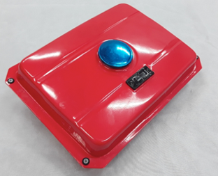 | 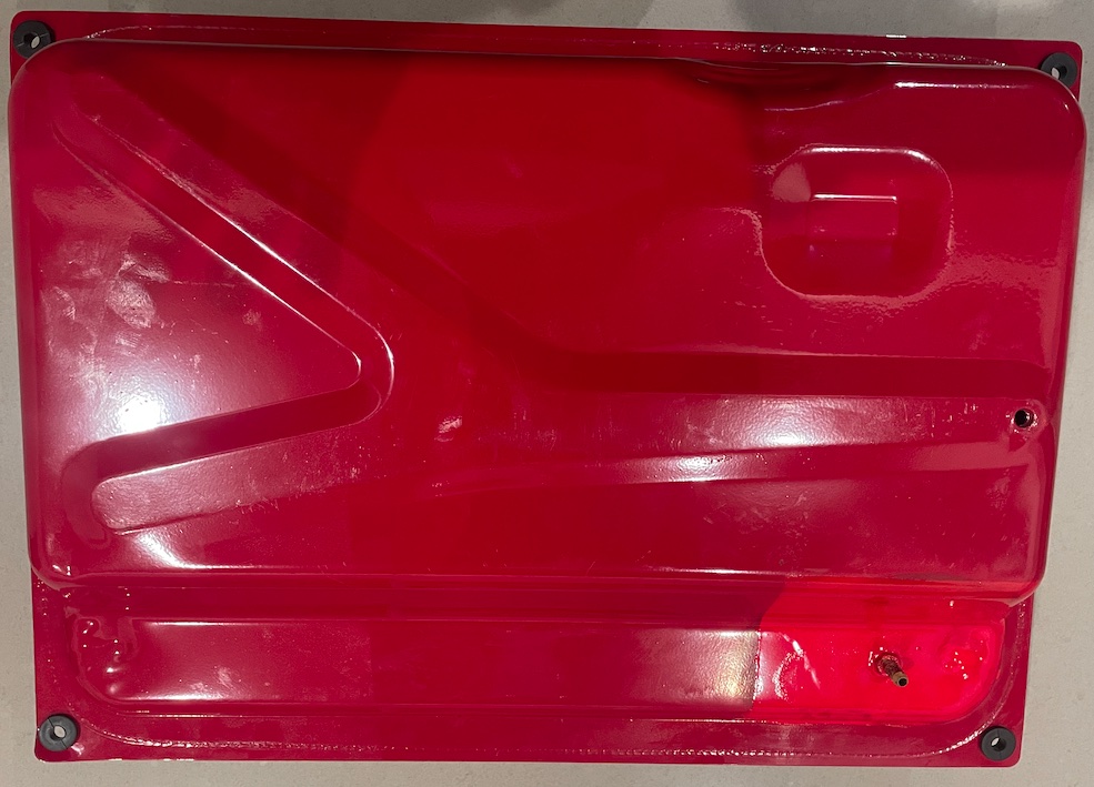 | 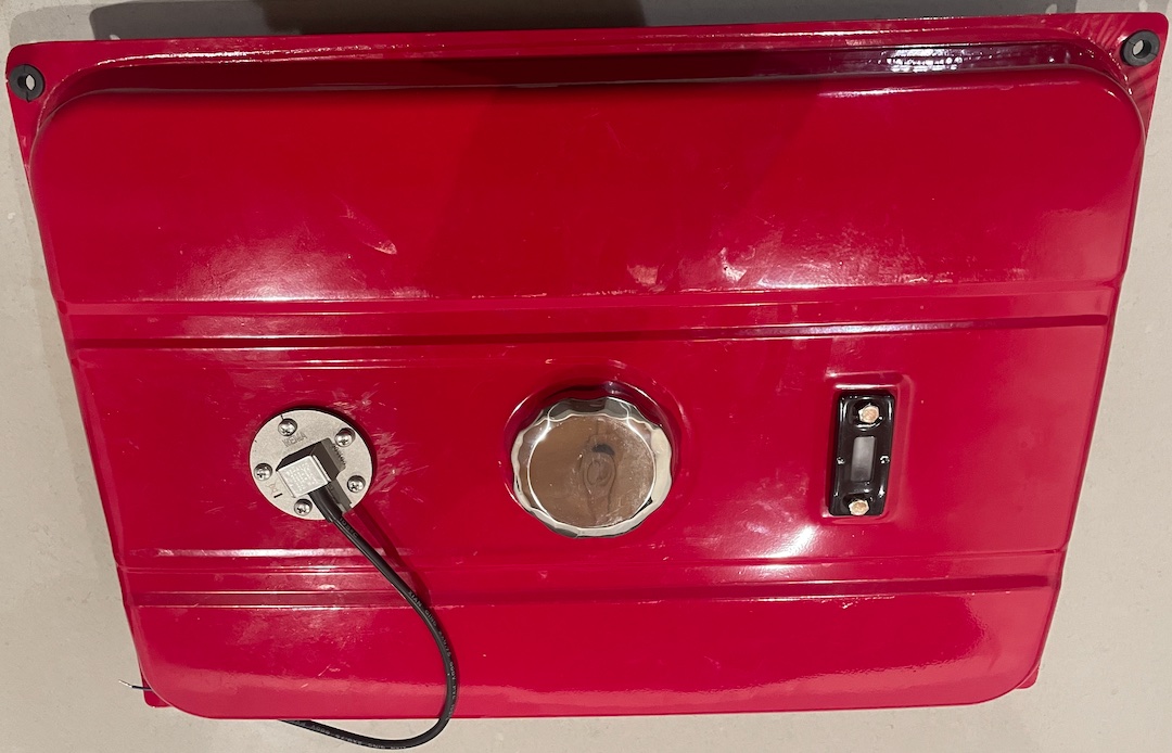 |
The pump now runs with the 13 L tank originally supplied and the 24 L tank, with its sender, mounted in a steel frame. The outlets of the 13 L and 24 L tanks, each with their own taps, are joined through a T barb. The sender's wiring and calibration are described in Sensors.
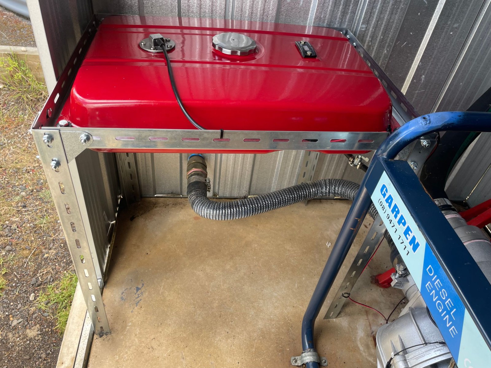
The tank outlet
In order to keep options open, the tank was ordered with a 65 mm outlet, but in the end it was decided that a DN50 outlet to DN50 pipes would be sufficient.
The five modes as first conceived
The system was designed to operate in five modes, controlled by four motorised valves and one solenoid valve. As first described: shed cooling only; high volume, to run for up to 30 minutes when the fire front is close or has arrived (say when the temperature sensor indicates more than 65 °C); low volume, for cinder attack prevention, capable of running for at least 3 hours; intermittent low volume; and low volume with gel injection. The present modes and figures are in The Water Control System: valves, flow modes and the pump shed.
Planning the intermittent spray mode
The early calculations showed, for example, that if the sprinklers were to run for 60 seconds on, then rest for 150 seconds before repeating the cycle, the 3.1 hours of available water would extend by a factor of 3.2 to 10 hours. To achieve this, a three-way motorised valve was placed between the low-flow system and the return-to-tank section of the test loop: normally open to the low-flow system, but switched on a cycle to the return line, remotely adjustable as circumstances demand.
The planning table (assuming a 30.3 kL tank starting full, low volume at 150 L/min, and no refilling):
| Spray time | Pause time | Duty cycle | Effective run time |
|---|---|---|---|
| 2 min | 2 min | 50% | 6 hours |
| 2 min | 4 min | 33% | 9 hours |
| 2 min | 8 min | 20% | 15 hours |
| 1 min | 4 min | 20% | 15 hours |
At that stage pump cycling was to be allowed when the battery was above 12.25 V and the cycle at least 5 minutes long, and the intermittent cycle was to respond to external temperature, the rate of temperature rise, ember trap activation, battery voltage, the time since the last ember detection, and manual settings. As the code developed, the rate of rise was dropped as a trigger, embers came to raise an alert only, and the thresholds changed to those now in use (see Autonomous Fire Defence Algorithms). The remote dashboard of the time was Blynk; it was later replaced by Home Assistant.
<< Development history | | Development history: sprinklers and pipework >> |Table of Contents>